

Inductive sensor NJ40+U4+W
Technical Data
General specifications
Switching element function AC NO/N C
Model Number
NJ40+U4+W
Features
• 40 mm non-flush
•2-wire AC
• Limit switch style housing
•Metal base 1/2" NPT
Accessories
MHW 01
Modular mounting bracket
Rated operating distance s
Installation non-flush
Output polarity AC
Assured operating distance sa0 ... 32.4 mm
Actual operating distance s
Reduction factor rAl 0.5
Reduction factor r
Reduction factor r
Nominal ratings
Operating voltage AC UB20 ... 253 V
Switching frequency f 0 ... 20 Hz
Hysteresis H 1 ... 10 typ. 5 %
Vol tag e d rop U
Momentary current
(20 ms, 0.1 Hz)
Operating current I
S
Off-state current I
Off-state current U
ment off I
Operating voltage indicator LED, green
Switching state indicator LED, yellow
Functional safety related parameters
MTTFd 760 a
Mission Time (TM) 20 a
Diagnostic Coverage (DC) 0 %
Ambient conditions
Ambient temperature -25 ... 70 °C (-13 ... 158 °F)
Storage temperature -25 ... 85 °C (-13 ... 185 °F)
Mechanical specifications
Connection type screw terminals
Information for connection A maximum of two conductors with the same core cross-section
Core cross-section up to 2.5 mm
Minimum core cross-section
Maximum core cross-section
Housing material PBT/metal
Sensing face PBT
Degree of protection IP68
Note
General information
Supplementary information Connection selectable as normally open or normally closed opera-
Compliance with standards and directives
Stan dard conf ormit y
Sta ndar ds
Approvals and certificates
UL approval cULus Listed, General Purpose
CSA approval cCSAus Listed, General Purpose
CCC approval Certified by China Compulsory Certification (CCC)
0.45
Cu
0.8
304
24 V, switching ele-
B
r
40 mm
n
36 ... 44 mm typ. 40 mm
r
1)
≤ 5 V
d
0 ... 3000 mA
8 ... 500 mA
L
0.5 ... 1.95 mA typ. 1.2 mA
r
0.5 ... 1.7 mA typ. 1.2 µA
may be mounted on one terminal connection!
tightening torque 1.2 Nm + 10 %
without wire end ferrule 0.5 mm
without wire end ferrule 2.5 mm2 , with connector sleeves 1.5 mm
1)
In the temperature range below 0 °C, permissible operating voltage U
Safety fuse ≤ 2 A (quick-blow) according to IEC 60127-2 Sheet 1
Recommendation: after a short circuit, check that the device is
functioning correctly.
tion.
Only wire one output per device.
EN 60947-5-2:2007
IEC 60947-5-2:2007
2
80...253 V
b
2
, with connector sleeves 0.34 mm
2
2
Release date: 2016-09-29 11:41 Date of issue: 2016-10-10 085592_eng.xml
Refer to “General Notes Relating to Pepperl+Fuchs Product Information”.
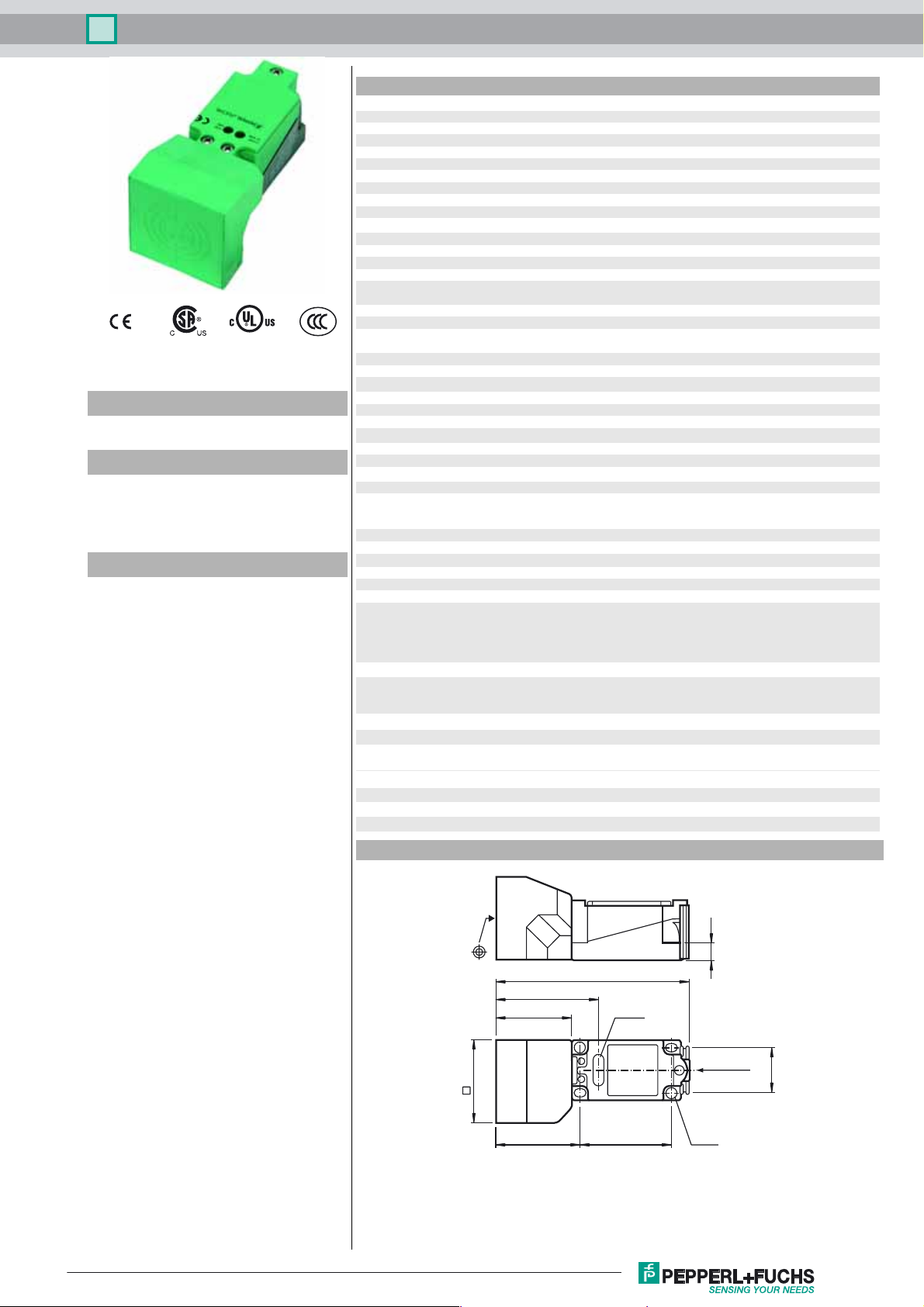
Dimensions
55
128
67.5
50
56 60
LED(s)
ø 5.5
11
½‘‘ NPT
30
1
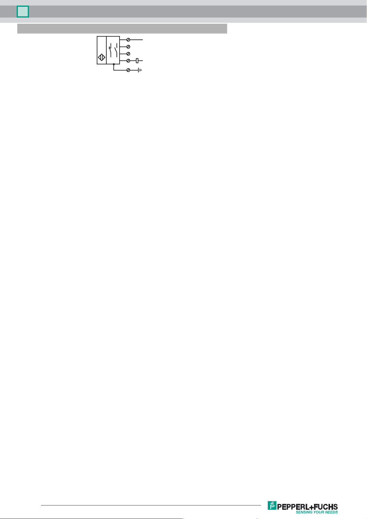
Inductive sensor NJ40+U4+W
Electrical Connection
3
1
4
2
L
N
Release date: 2016-09-29 11:41 Date of issue: 2016-10-10 085592_eng.xml
Refer to “General Notes Relating to Pepperl+Fuchs Product Information”.
2
 Loading...