

Pepperl Fuchs NJ40P-FP-A2-P1 Data Sheet
Inductive sensor NJ40P-FP-A2-P1
Technical Data
General specifications
Switching element function PNP NO/NC
Model Number
NJ40P-FP-A2-P1
Features
•Comfort series
• 40 mm non-flush
• Only for non-ferrous metals
Rated operating distance s
Installation non-flush
Output polarity DC
Assured operating distance sa1 ... 32.4 mm
Reduction factor r
Reduction factor rCu 1
Reduction factor r
Reduction factor r
Nominal ratings
Operating voltage UB10 ... 30 V
Switching frequency f 0 ... 150 Hz
Hysteresis H 3 ... 10 %
Reverse polarity protection reverse polarity protected
Short-circuit protection pulsing
Vol tag e d rop U
Operating current I
No-load supply current I
Time delay before availability t
Operating voltage indicator LED, green
Switching state indicator LED, yellow
Ambient conditions
Ambient temperature -25 ... 70 °C (-13 ... 158 °F)
Mechanical specifications
Connection type screw terminals
Information for connection A maximum of two conductors with the same core cross-section
Core cross-section up to 2.5 mm
Minimum core cross-section
Maximum core cross-section
Housing material PBT
Sensing face PBT
Degree of protection IP68
Compliance with standards and directives
Stan dard conf ormit y
Sta ndar ds
Approvals and certificates
UL approval cULus Listed, General Purpose
CSA approval cCSAus Listed, General Purpose
1
Al
0
St37
1
Brass
40 mm
n
≤ 3 V
d
0 ... 200 mA
L
≤ 20 mA
0
≤ 10 ms
v
may be mounted on one terminal connection!
tightening torque 1.2 Nm + 10 %
without wire end ferrule 0.5 mm
without wire end ferrule 2.5 mm2 , with connector sleeves 1.5 mm
EN 60947-5-2:2007
IEC 60947-5-2:2007
2
2
, with connector sleeves 0.34 mm
2
2
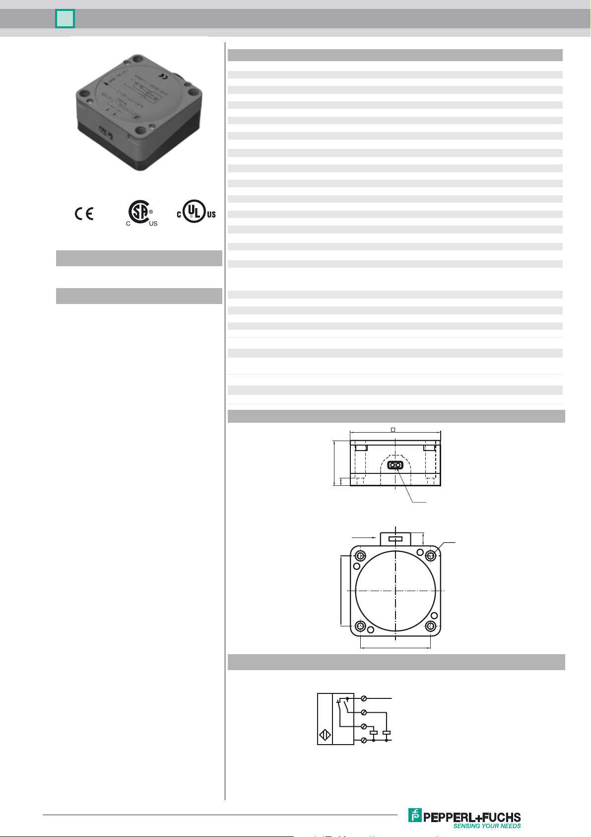
Dimensions
Electrical Connection
80
40
7
LEDs
65
M20 x 1,5
1
65
L+
Ø5,3
11
4
2
3
L-
Release date: 2016-09-29 11:43 Date of issue: 2016-10-10 020228_eng.xml
Refer to “General Notes Relating to Pepperl+Fuchs Product Information”.
1
 Loading...