

Inductive sensor NEB6-12GM50-E0-V1
Technical Data
General specifications
Switching element function NPN NO
Model Number
NEB6-12GM50-E0-V1
Features
• Increased operating distance
•6 mm flush
Accessories
BF 12
Mounting flange, 12 mm
V1-G
Female connector, M12, 4-pin, field attachable
V1-W
Female connector, M12, 4-pin, field attachable
V1-G-2M-PUR
Female cordset, M12, 4-pin, PUR cable
V1-W-2M-PUR
Female cordset, M12, 4-pin, PUR cable
Rated operating distance s
Installation quasi flush
Output polarity DC
Assured operating distance sa0 ... 4.8 mm
Actuating element mild steel, e. g. 1.0037, SR235JR (formerly St37-2)
Reduction factor rAl 0.28
Reduction factor r
Reduction factor r
Reduction factor r
Nominal ratings
Installation conditions
A
B
C
F
Operating voltage UB10 ... 30 V DC
Switching frequency f 0 ... 800 Hz
Hysteresis H 0.06 ... 1.2 mm
Reverse polarity protection yes
Short-circuit protection pulsing
Overload resistance yes
Wire breakage protection yes
Surge suppression yes
Ripple 10 %
Vol tag e d rop U
Repeat accuracy R 0.3 mm
Operating current I
Off-state current I
No-load supply current I
Time delay before availability t
Switching state indicator LED, yellow
Functional safety related parameters
MTTFd 1740 a
Mission Time (TM) 20 a
Diagnostic Coverage (DC) 0 %
Ambient conditions
Ambient temperature -25 ... 85 °C (-13 ... 185 °F)
Storage temperature -40 ... 85 °C (-40 ... 185 °F)
Mechanical specifications
Connection type Connector M12 x 1 , 4-pin
Housing material brass, nickel-plated
Sensing face PBT
Degree of protection IP67
Mass 20 g
Compliance with standards and directives
Stan dard conf ormit y
Sta ndar ds
Approvals and certificates
EAC conformity TR CU 020/2011
UL approval cULus Listed, General Purpose
CCC approval CCC approval / marking not required for products rated ≤36 V
0.2
Cu
0.7
304
0.35
Brass
6 mm
n
18 mm x 18 mm x 1 mm
in steel 1.0037 (St37): 2.4 mm
in other metal: 1.2 mm
12 mm
18 mm
24 mm
≤ 2 V
d
0 ... 200 mA , above 70°C ≤ 150 mA
L
≤ 10 µA
r
≤ 15 mA
0
≤ 50 ms
v
EN 60947-5-2:2007
IEC 60947-5-2:2007
Release date: 2016-06-17 10:01 Date of issue: 2016-06-17 231713_eng.xml
Refer to “General Notes Relating to Pepperl+Fuchs Product Information”.
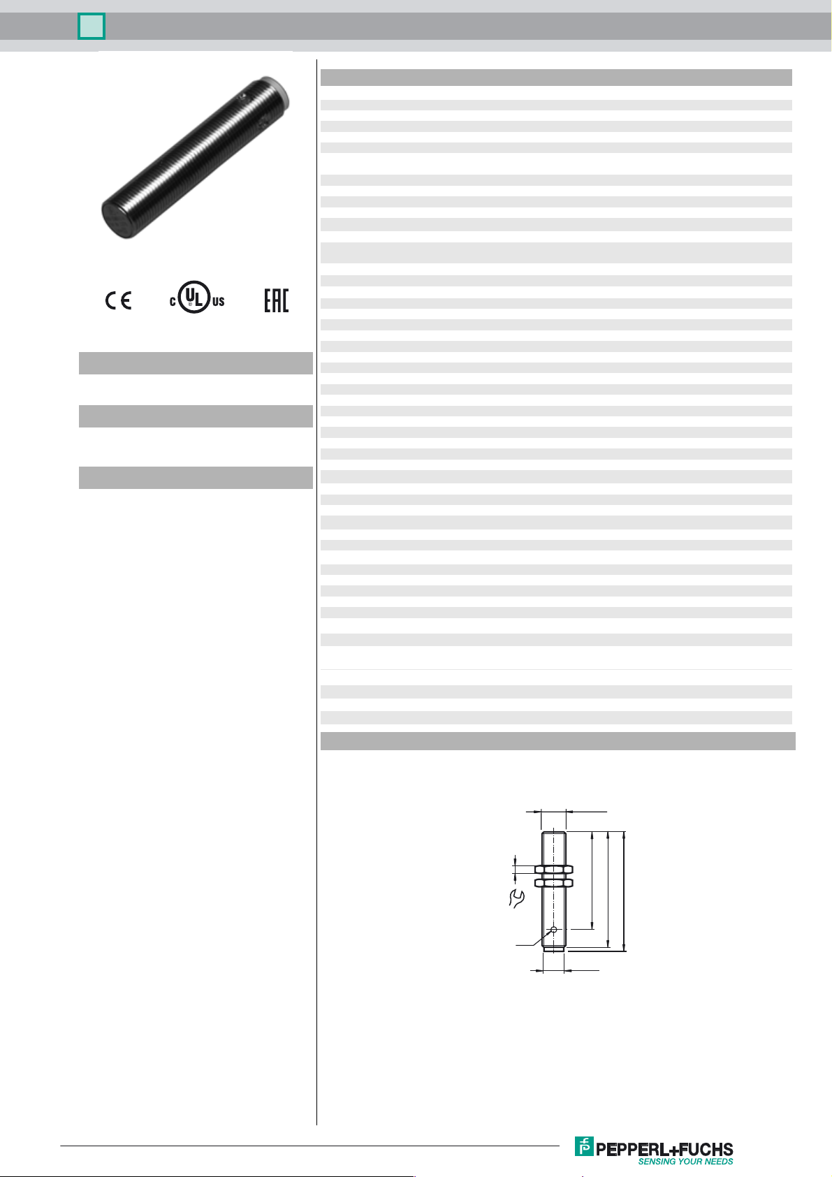
Dimensions
4
LED
17
M12 x 1
49.5
ø 10.5
58
60
1
Inductive sensor NEB6-12GM50-E0-V1
Electrical Connection
Pinout
1
4
3
Wire colors in accordance with EN 60947-5-2
1 BN
2 WH
3 BU
4 BK
2
L+
L-
1
4
3
(brown)
(white)
(blue)
(black)
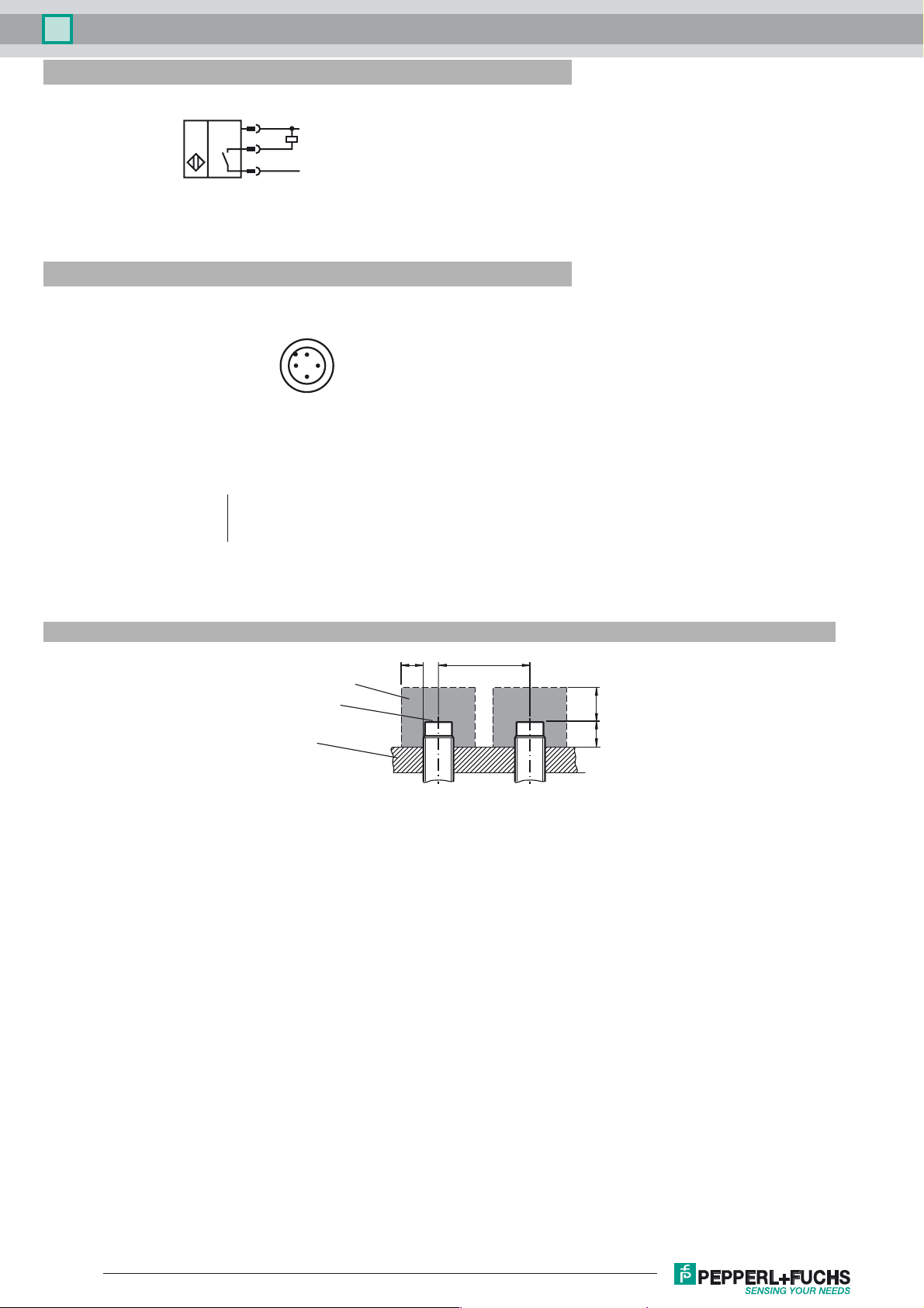
Installation Conditions
metal-free zone
sensing face
support
B F
CA
Release date: 2016-06-17 10:01 Date of issue: 2016-06-17 231713_eng.xml
Refer to “General Notes Relating to Pepperl+Fuchs Product Information”.
2
 Loading...