

Inductive sensor NCN8-18GM60-B3B-V1
Technical Data
General specifications
Switching function Normally open/closed (NO/NC) programmable
Output type AS-Interface
Rated operating distance sn8 mm
Installation non-flush
Assured operating distance sa0 ... 6.48 mm
Model Number
NCN8-18GM60-B3B-V1
Features
•Comfort series
• 8 mm non-flush
• A/B slave with extended addressing
possibility for up to 62 slaves
• Cylindrical
•NO/NC selectable
• Stability control warning
• Installation help
• On/Off delay (disconnectable)
• Oscillator monitoring
Accessories
BF 18
Mounting flange, 18 mm
V1-G
Female connector, M12, 4-pin, field attachable
V1-W-2M-PUR
Female cordset, M12, 4-pin, PUR cable
V1-G-2M-PUR
Female cordset, M12, 4-pin, PUR cable
V1-W
Female connector, M12, 4-pin, field attachable
Actual operating distance s
Reduction factor rAl 0.42
Reduction factor r
Reduction factor r
Slave type A/B slave
AS-Interface specification V3.0
Required master specification ≥ V2.1
Output type 2-wire
Nominal ratings
Operating voltage UB26.5 ... 31.9 V via AS-i bus system
Switching frequency f 0 ... 100 Hz
Hysteresis H 1 ... 15 typ. 5 %
Reverse polarity protection reverse polarity protected
Vol tag e d rop at IL
Vol tag e dr op I
on U
d
Time delay before availability t
Operating voltage indicator dual-LED, green
Switching state indicator dual-LED, yellow/red
Error indicator dual-LED, red
Functional safety related parameters
MTTFd 926 a
Mission Time (TM) 20 a
Diagnostic Coverage (DC) 0 %
Ambient conditions
Ambient temperature -25 ... 70 °C (-13 ... 158 °F)
Storage temperature -40 ... 85 °C (-40 ... 185 °F)
Mechanical specifications
Connection type Connector M12 x 1 , 4-pin
Housing material Stainless steel 1.4305 / AISI 303
Sensing face PBT
Degree of protection IP67
Compliance with standards and directives
Stan dard conf ormit y
Electromagnetic compatibility
Sta ndar ds
Approvals and certificates
UL approval cULus Listed, General Purpose
CSA approval cCSAus Listed, General Purpose
CCC approval CCC approval / marking not required for products rated ≤36 V
0.4
Cu
0.72
304
= 20 mA, switching element
L
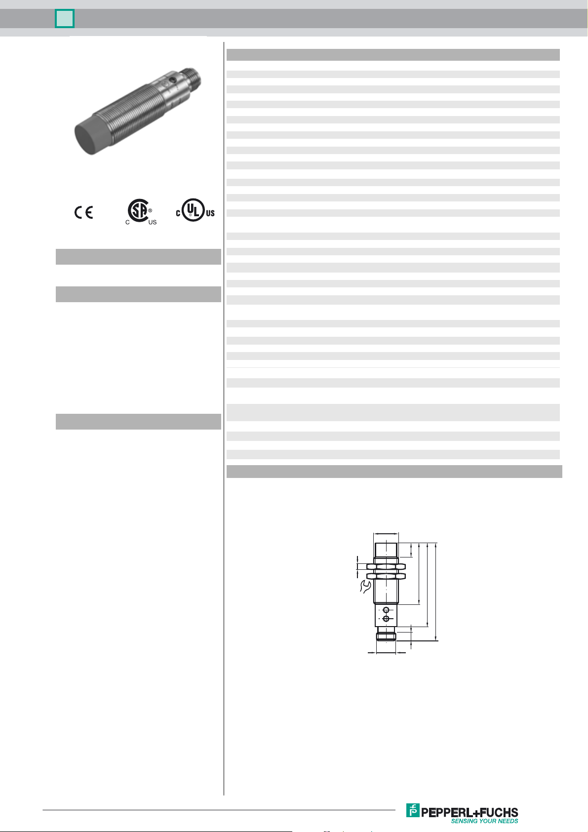
Dimensions
7.2 ... 8.8 mm typ. 8 mm
r
3.4 ... 5 V typ. 4.3 V
≤ 1000 ms
v
EN 50295:1999-10
EN 60947-5-2:2007
IEC 60947-5-2:2007
Release date: 2017-05-03 09:42 Date of issue: 2017-05-03 230829_eng.xml
Refer to “General Notes Relating to Pepperl+Fuchs Product Information”.
M18x1
10
4
24
M12x1
44
60
70
6
1
Inductive sensor NCN8-18GM60-B3B-V1
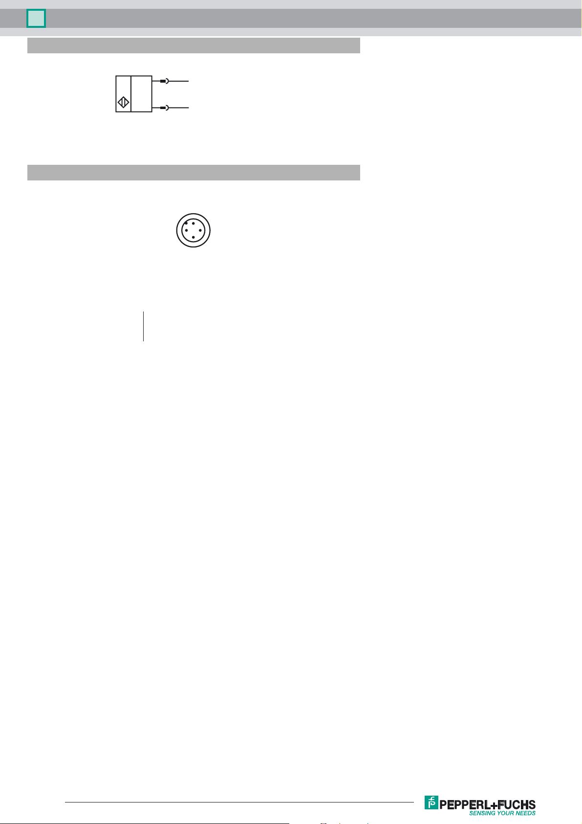
Electrical Connection
Pinout
1
3
Wire colors in accordance with EN 60947-5-2
1 BN
2 WH
3 BU
4 BK
2
(+)
(-)
1
4
3
(brown)
(white)
(blue)
(black)
Release date: 2017-05-03 09:42 Date of issue: 2017-05-03 230829_eng.xml
Refer to “General Notes Relating to Pepperl+Fuchs Product Information”.
2

Inductive sensor NCN8-18GM60-B3B-V1
Programming Instructions
Adress 00 preset, alterable
via Busmaster
or programming units
IO-Code 0
ID-Code A
ID1-Code 7
ID2-Code E
Data bit
Bit Function
D0 Switching state
D1 Prefailure message (dynamic)
D2 Oscillator monitoring
D3 Object too close
Parameter bit
Bit Function
P0 ON / Off delay
activated* / deactivated
P1 Switching element function
NO* / NC
P2 not used
P3 not used
*
Indicators
Standard setting
LED red
UAI
LED red
FAULT
LED yellow
OUT
LED green
POWER
Release date: 2017-05-03 09:42 Date of issue: 2017-05-03 230829_eng.xml
Refer to “General Notes Relating to Pepperl+Fuchs Product Information”.
3

Inductive sensor NCN8-18GM60-B3B-V1
Indication depending on the distance to the object and switching element function (P1)
Distance to the
object
> 1.2 S
n
1 Sn - 1.2 S
0.8 S
0.1 S
0 Sn - 0.1 S
> 1,2 S
1 S
n
0.8 Sn - 1 S
0.1 S
0 S
n
- 1 S
n
- 0.8 S
n
n
- 1.2 S
- 0.8 S
n
- 0.1 S
n
n
n
n
n
n
n
n
Function Parameter
P1
yellow LED
(OUT)
red LED
(UAI)
Data bit
D0
NO 1 off off 0 1
1 off flashing 0 1
1 flashing flashing 1 1
1onoff11
1 flashing flashing 1 0
NC 0 on off 1 1
0 flashing flashing 1 1
0 off flashing 0 1
0offoff01
0 off flashing 1 0
Data bit
D3
Indication depending on the operation mode
Symptoms green LED
(POWER)
red LED
(FAULT)
Data bit
D2
normal operation on off 1
oscillator defect flashing flashing 0*
no communication off on 1
*: D0, D1, D3 will be set to 0
Dynamic pre-fault indication:
While normal operation D1=1. If the switch is damped critically, i.e. the object has passed uncompletely the unsafe sensing
range of 0.8 S
- 1.2 sn during damping, changes D1 to 0 and signals that an adjustment is necessary. See the following dia-
n
gram:
Monitoring "object too near":
D3 serves as signalling: Object too near too the sensor, danger of damage, adjustment necessary. In normal mode D3=1.
If the object reaches the 0 - 0.1 sn range, D3=0. If the object leaves this range, D3=1.
On/off delay:
The on/off delay is preset and switched on (P0=1). On delay approx.15 ms, when P0=1 and NO function (P1=1). Off delay
approx.15 ms, when P0=1 and NC function (P1=0).
Release date: 2017-05-03 09:42 Date of issue: 2017-05-03 230829_eng.xml
Refer to “General Notes Relating to Pepperl+Fuchs Product Information”.
4
 Loading...