

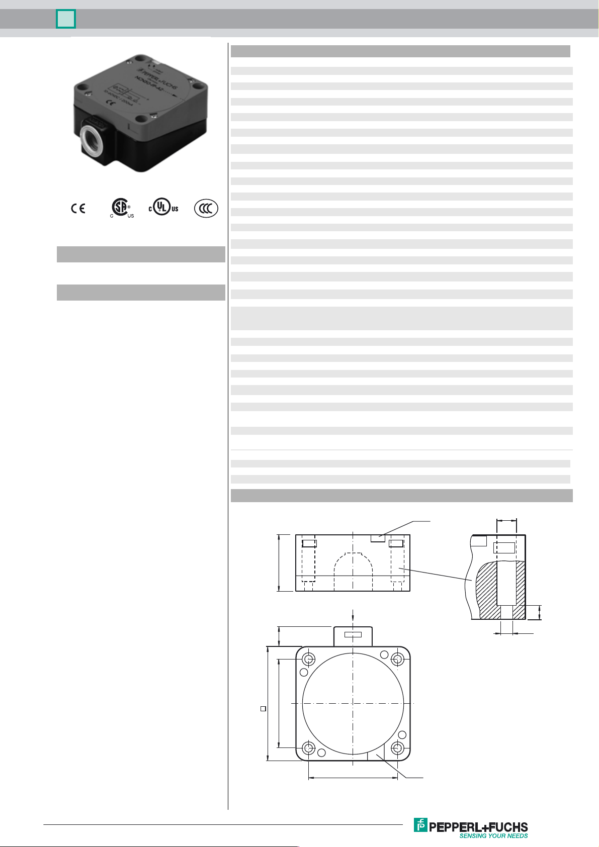
Inductive sensor NCN50-FP-A2-P1-3G-3D
Technical Data
General specifications
Switching function complementary
Output type PNP
Rated operating distance sn50 mm
Installation non-flush
Output polarity DC
Model Number
NCN50-FP-A2-P1-3G-3D
Features
• 50 mm non-flush
•4-wire DC
• ATEX-approval for zone 2 and zone 22
Assured operating distance s
Reduction factor rAl 0.4
Reduction factor r
Reduction factor r
Output type 4-wire
Nominal ratings
Operating voltage UB10 ... 60 V DC
Switching frequency f 0 ... 80 Hz
Hysteresis H typ. 3 %
Reverse polarity protection reverse polarity protected
Voltage drop U
Operating current I
S
Off-state current I
No-load supply current I
Time delay before availability t
Operating voltage indicator LED, green
Switching state indicator LED, yellow
Functional safety related parameters
MTTFd 671 a
Mission Time (TM) 20 a
Diagnostic Coverage (DC) 0 %
Ambient conditions
Ambient temperature -25 ... 70 °C (-13 ... 158 °F)
Mechanical specifications
Connection type screw terminals
Information for connection A maximum of two conductors with the same core cross section
Core cross-section up to 2.5 mm
Minimum core cross-section
Maximum core cross-section
Housing material PBT
Sensing face PBT
Housing base PBT
Degree of protection IP67
General information
Use in the hazardous area see instruction manuals
Category
Compliance with standards and
directives
Standard conformity
Standards
Approvals and certificates
UL approval cULus Listed, General Purpose
CSA approval cCSAus Listed, General Purpose
CCC approval Certified by China Compulsory Certification (CCC)
Cu
304
Dimensions
0.3
0.85
0 ... 40.5 mm
a
≤ 3 V
d
0 ... 200 mA
L
0 ... 0.5 mA
r
≤ 20 mA
0
≤ 300 ms
v
may be mounted on one terminal connection!
tightening torque 1.2 Nm + 10 %
without wire end ferrule 0.5 mm2 , with connector sleeves 0.34 mm
without wire end ferrule 2.5 mm
3G; 3D
EN 60947-5-2:2007
IEC 60947-5-2:2007
2
2
, with connector sleeves 1.5 mm
2
2
Release date: 2018-05-09 12:54 Date of issue: 2018-05-09 129434_eng.xml
Refer to “General Notes Relating to Pepperl+Fuchs Product Information”.
LEDs
ø 9.5
40
M20 x 1.5
7
ø 5.3
11
80
65
65
LEDs
1
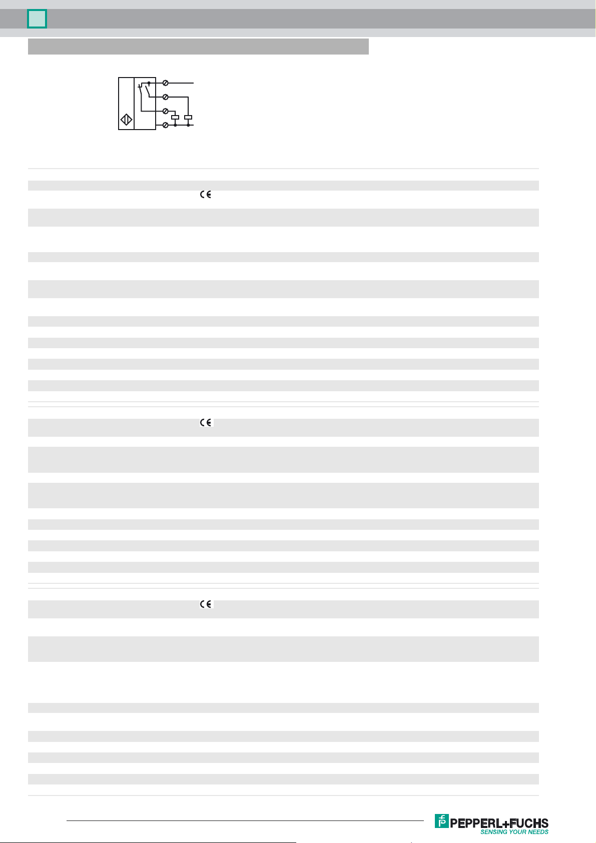
Inductive sensor NCN50-FP-A2-P1-3G-3D
Electrical Connection
1
L+
4
2
3
L-
Equipment protection level Gc (nA)
Certificate PF 15CERT3754 X
CE marking
ATEX marking ¬ II 3G Ex nA IIC T6 Gc
Standards EN 60079-0:2012+A11:2013, EN 60079-15:2010
The Ex-related marking can also be printed on the enclosed label.
Ignition protection category "n"
Use is restricted to the following stated conditions
Special conditions
Maximum operating current I
Maximum operating voltage U
L
Bmax
Maximum permissible ambient temperature T
at U
at U
at U
at U
at U
at U
at U
at U
=60 V, IL=200 mA
Bmax
=60 V, IL=100 mA
Bmax
=60 V, IL=50 mA
Bmax
=60 V, IL=25 mA
Bmax
=30 V, IL=200 mA
Bmax
=30 V, IL=100 mA
Bmax
=30 V, IL=50 mA
Bmax
=30 V, IL=25 mA
Bmax
The maximum permissible load current must be restricted to the values given in the following list. High load currents
and load short-circuits are not permitted.
The maximum permissible operating voltage UB max is restricted to the values in the following list. Tolerances are
not permissible.
dependant of the load current I
Umax
Information can be taken from the following list.
and the max. operating voltage U
L
44 °C (111.2 °F)
45 °C (113 °F)
48 °C (118.4 °F)
48 °C (118.4 °F)
51 °C (123.8 °F)
55 °C (131 °F)
56 °C (132.8 °F)
57 °C (134.6 °F)
Equipment protection level Dc
CE marking
Bmax
ATEX marking ¬ II 3D IP67 T 96 °C (204.8 °F) X
Standards EN 50281-1-1
Protection via housing
Use is restricted to the following stated conditions
Special conditions
Maximum heating (Temperature rise)
at U
at U
at U
at U
at U
at U
at U
=60 V, IL=200 mA
Bmax
=60 V, IL=100 mA
Bmax
=60 V, IL=50 mA
Bmax
=60 V, IL=25 mA
Bmax
=30 V, IL=200 mA
Bmax
=30 V, IL=100 mA
Bmax
=30 V, IL=50 mA
Bmax
dependant of the load current IL and the max. operating voltage U
Information can be taken from the following list. The maximum surface temperature at maximum ambient
temperature is given in the Ex identification of the apparatus.
Bmax
26 K
25 K
22 K
22 K
19 K
15 K
13 K
Equipment protection level Dc (tc)
CE marking
ATEX marking ¬ II 3D Ex tc IIIC T80°C Dc
Standards EN 60079-0:2012+A11:2013, EN 60079-31:2014
General The corresponding datasheets, declarations of conformity, EC-type examination certificates, certifications, and
The Ex-related marking can also be printed on the enclosed label.
Protection by enclosure "tc" Some of the information in this instruction manual is more specific than the information
provided in the datasheet.
control draw see datasheets), form an integral part of this document. These documents can
be found at The maximum surface temperature of the device was determined without a
layer of dust of the information in this instruction manual is more specific than the
information provided in the datasheet.
Special conditions
dependant of the load current I
Maximum permissible ambient temperature T
at U
at U
at U
at U
at U
at U
=60 V, IL=200 mA
Bmax
=60 V, IL=100 mA
Bmax
=60 V, IL=50 mA
Bmax
=60 V, IL=25 mA
Bmax
=30 V, IL=200 mA
Bmax
=30 V, IL=100 mA
Bmax
Refer to “General Notes Relating to Pepperl+Fuchs Product Information”.
Umax
Information can be taken from the following list.
44 °C (111.2 °F)
45 °C (113 °F)
48 °C (118.4 °F)
48 °C (118.4 °F)
51 °C (123.8 °F)
55 °C (131 °F)
and the max. operating voltage U
L
Bmax
2
Release date: 2018-05-09 12:54 Date of issue: 2018-05-09 129434_eng.xml
 Loading...