

Inductive sensor NCN4-12GM60-B3B-C2-V1
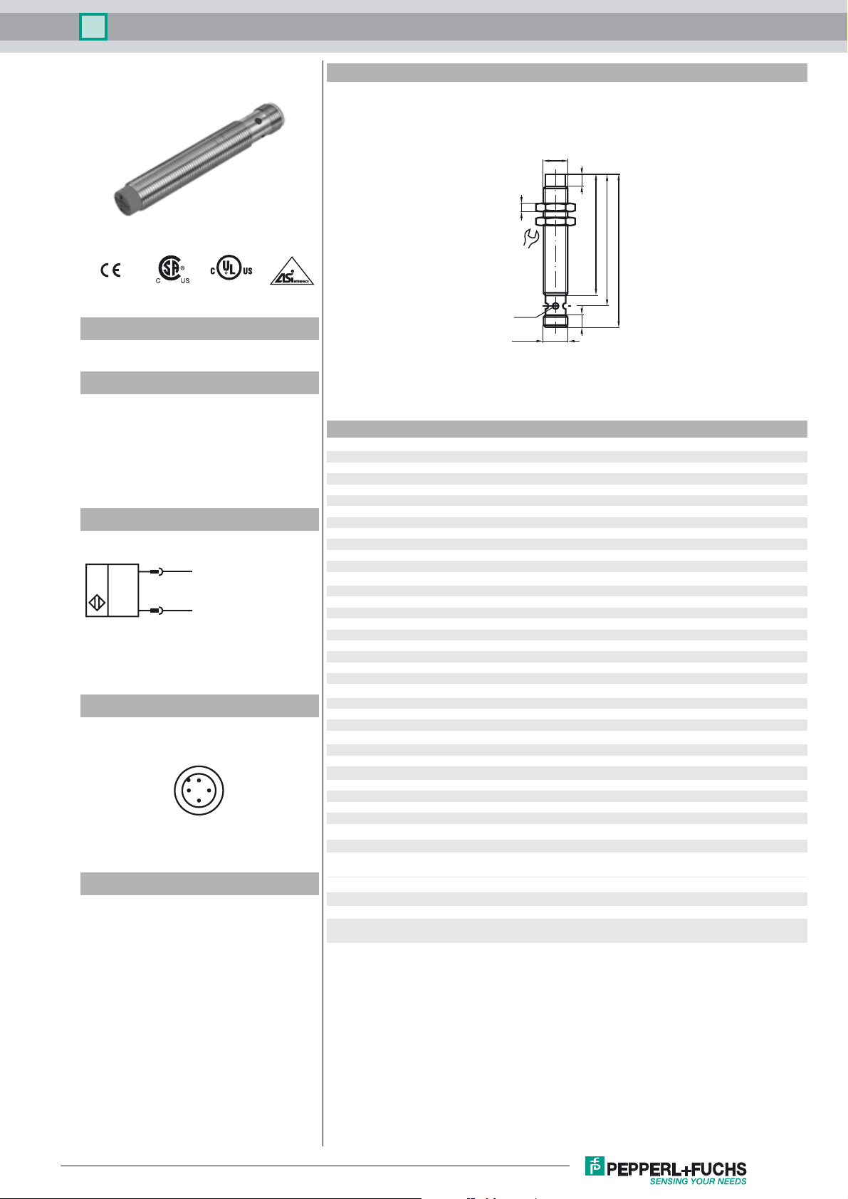
Dimensions
M12x1
5
4
Model Number
NCN4-12GM60-B3B-C2-V1
Features
• Comfort series
• 4 mm non-flush
• A/B slave with extended addressing
possibility for up to 62 slaves
• Cylindrical
• NO/NC selectable
• On/Off delay (disconnectable)
Connection
1
3
(+)
(-)
Pinout
1
2
4
3
Accessories
BF 12
Mounting flange, 12 mm
V1-G
4-pin, M12 female field-attachable connector
EXG-12
Quick mounting bracket with dead stop
V1-W
4-pin, M12 female field-attachable connector
V1-W-2M-PUR
Cable socket, M12, 4-pin, PUR cable
V1-G-2M-PUR
Cable socket, M12, 4-pin, PUR cable
17
LED
M12x1
60
65
75
6
Technical Data
General specifications
Switching element function NO/NC programmable
Rated operating distance s
Installation non-flush
Output polarity AS-Interface
Assured operating distance sa0 ... 3.24 mm
Reduction factor r
Reduction factor rCu 0.36
Reduction factor r
Slave type A/B slave
AS-Interface specification V3.0
Required master specification ≥ V2.1
Nominal ratings
Operating voltage UB26.5 ... 31.9 V via AS-i bus system
Switching frequency f 0 ... 500 Hz
Hysteresis H 1 ... 15 typ. 5 %
Reverse polarity protection reverse polarity protected
No-load supply current I
Time delay before availability t
Alternating magnetic field B 100 mT
Indication of the switching state dual-LED, yellow
Fault indication dual-LED, red
Functional safety related parameters
MTTFd 2140 a
Mission Time (T
Diagnostic Coverage (DC) 0 %
Ambient conditions
Ambient temperature -25 ... 70 °C (-13 ... 158 °F)
Storage temperature -40 ... 85 °C (-40 ... 185 °F)
Mechanical specifications
Connection type Device connector M12 x 1 , 4-pin
Housing material Stainless steel 1.4305 / AISI 303
Sensing face PBT
Protection degree IP67
Compliance with standards and directives
Standard conformity
Standards
Approvals and certificates
UL approval cULus Listed, General Purpose
CSA approval cCSAus Listed, General Purpose
CCC approval Products with a maximum operating voltage of ≤36 V do not bear a
0.37
Al
0.74
304
) 20 a
M
4 mm
n
≤ 25 mA
0
≤ 1000 ms
v
EN 60947-5-2:2007
IEC 60947-5-2:2007
CCC marking because they do not require approval.
Release date: 2012-11-15 11:24 Date of issue: 2012-11-15 226329_eng.xml
Subject to modifications without notice
Copyright Pepperl+Fuchs
1
Inductive sensor NCN4-12GM60-B3B-C2-V1
Programming Instructions
Adress 00 preset, alterable
via Busmaster
or programming units
IO-Code 0
ID-Code A
ID1-Code 7
ID2-Code E
Data bit
Bit Function
D0 Switching state
D1 not used
D2 not used
D3 not used
Parameter bit
Bit Function
P0 ON / Off delay
activated* / deactivated
P1 Switching element function
NO* / NC
P2 not used
P3 not used
*
Standard setting
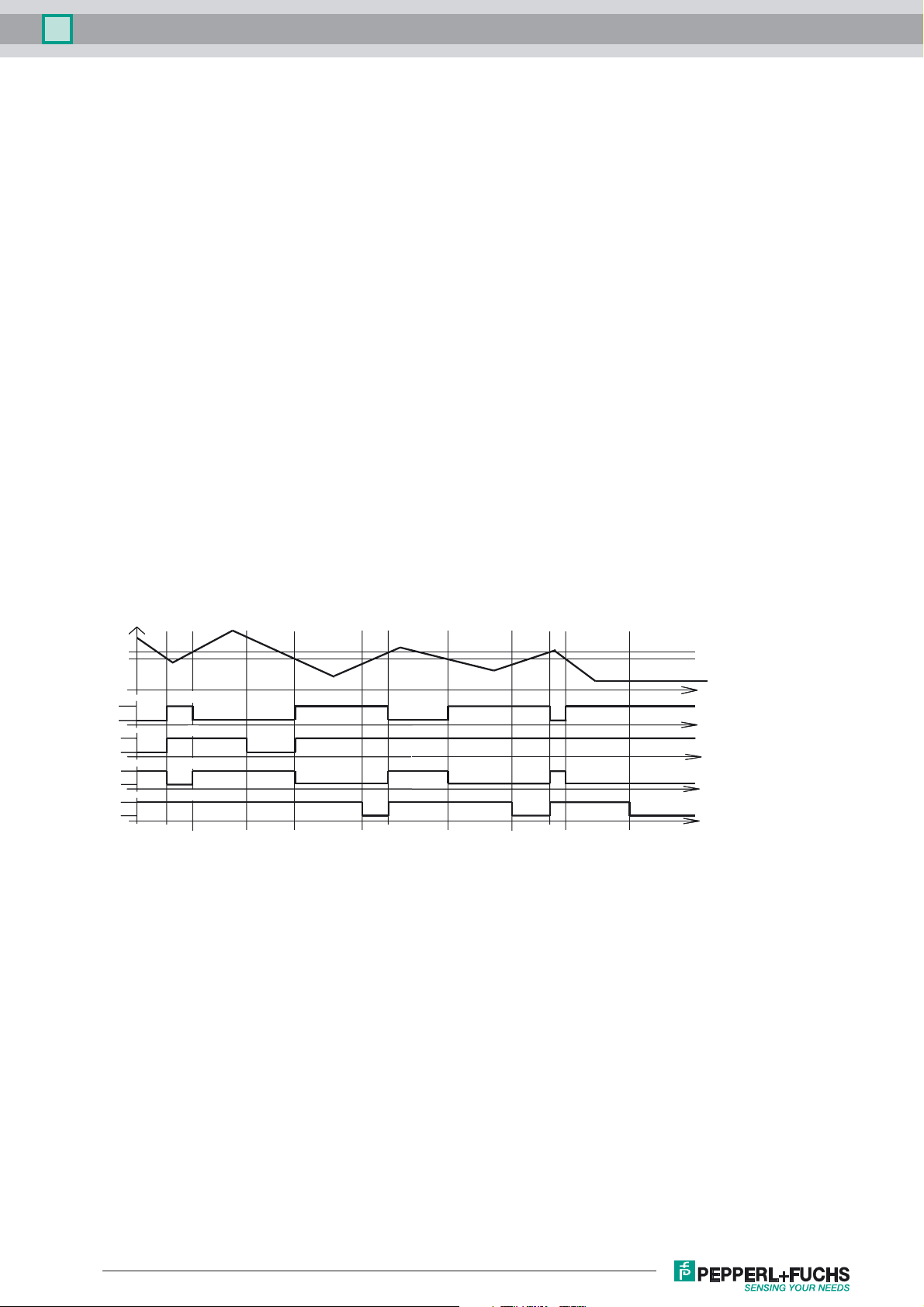
On/off delay:
Object distance
+ Hys.
S
n
1 S
n
P0 = 0
P1 = 1
P0 = 1
P1 = 1
P0 = 0
P1 = 0
P0 = 1
P1 = 0
H
L
H
L
H
L
H
Data bit D0
Data bit D0
Data bit D0
Data bit D0
L
t
t0 + 15 ms t1 + 15 ms t
0
t
1
2
t2 + 15 ms t
t3 + 15 ms
3
time
time
time
time
time
The on/off delay is preset and switched on (P0=1). On delay approx.15 ms, when P0=1 and NO function (P1=1). Off delay
approx.15 ms, when P0=1 and NC function (P1=0).
Release date: 2012-11-15 11:24 Date of issue: 2012-11-15 226329_eng.xml
Subject to modifications without notice
Copyright Pepperl+Fuchs
2
 Loading...