

Inductive sensor NCN4-12GM40-Z0-V1
Technical Data
General specifications
Switching element function DC NO
Model Number
NCN4-12GM40-Z0-V1
Features
• 4 mm non-flush
•2-wire DC
Accessories
BF 12
Mounting flange, 12 mm
V1-G
Female connector, M12, 4-pin, field attachable
V1-W
Female connector, M12, 4-pin, field attachable
V1-W-2M-PUR
Female cordset, M12, 4-pin, PUR cable
V1-G-2M-PUR
Female cordset, M12, 4-pin, PUR cable
Rated operating distance s
Installation non-flush
Output polarity DC
Assured operating distance sa0 ... 3.24 mm
Actual operating distance s
Reduction factor rAl 0.42
Reduction factor r
Reduction factor r
Nominal ratings
Operating voltage UB5 ... 60 V
Switching frequency f 0 ... 800 Hz
Hysteresis H 1 ... 10 typ. 5 %
Reverse polarity protection reverse polarity tolerant
Short-circuit protection pulsing
Vol tag e d rop U
Vol tag e d rop at IL
S
Vol tag e dr op I
on U
d
Operating current I
Off-state current I
Time delay before availability t
Switching state indicator Multihole-LED, yellow
Functional safety related parameters
MTTFd 2020 a
Mission Time (TM) 20 a
Diagnostic Coverage (DC) 0 %
Ambient conditions
Ambient temperature -25 ... 70 °C (-13 ... 158 °F)
Mechanical specifications
Connection type Connector M12 x 1 , 4-pin
Housing material Stainless steel 1.4305 / AISI 303
Sensing face PBT
Degree of protection IP67
Compliance with standards and directives
Stan dard conf ormit y
Sta ndar ds
Approvals and certificates
UL approval cULus Listed, General Purpose
CSA approval cCSAus Listed, General Purpose
CCC approval Certified by China Compulsory Certification (CCC)
0.4
Cu
0.75
304
= 10 mA, switching element
L
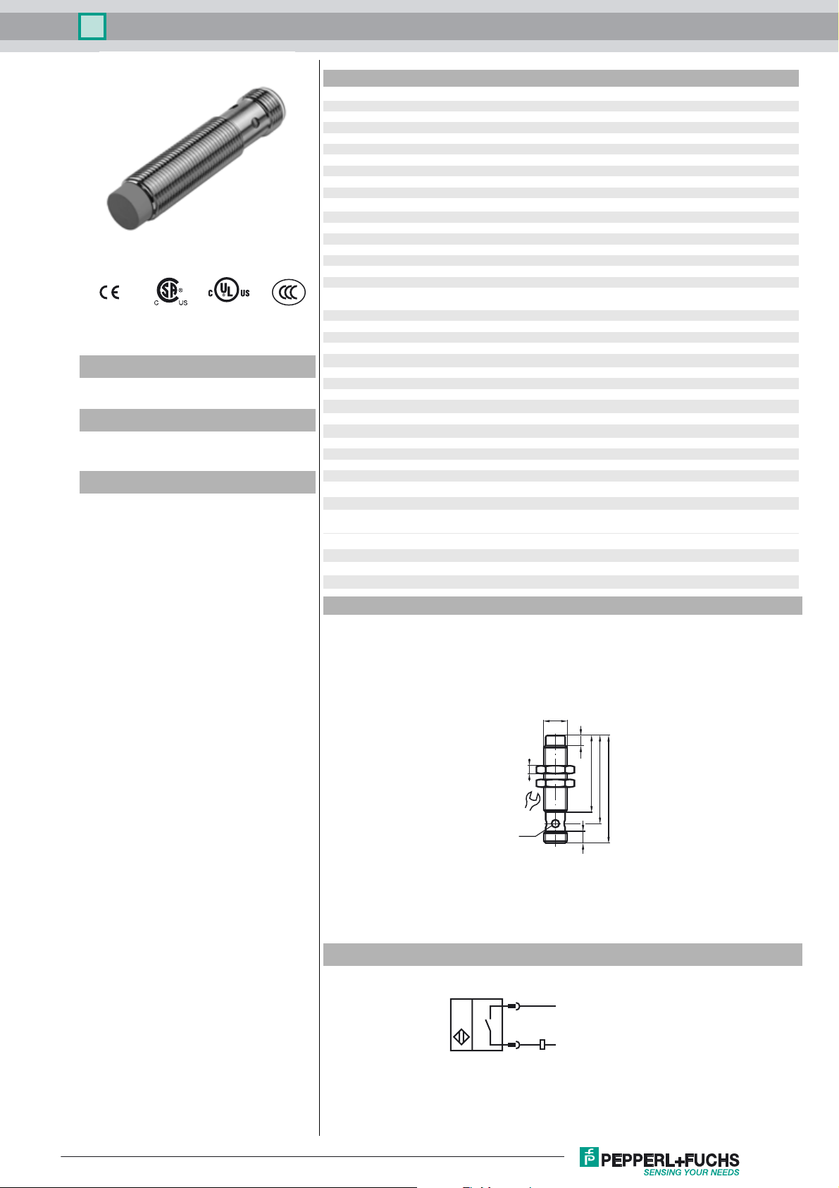
Dimensions
4 mm
n
3.6 ... 4.4 mm typ.
r
≤ 5 V
d
3.5 ... 4.7 V typ. 4.3 V
2 ... 100 mA
L
0 ... 0.5 mA typ.
r
≤ 15 ms
v
EN 60947-5-2:2007
IEC 60947-5-2:2007
Electrical Connection
M12x1
4
17
LED
3
4
5
39
45
55
6
L+
L-
Release date: 2012-05-21 11:06 Date of issue: 2016-01-07 126070_eng.xml
Refer to “General Notes Relating to Pepperl+Fuchs Product Information”.
1
Inductive sensor NCN4-12GM40-Z0-V1
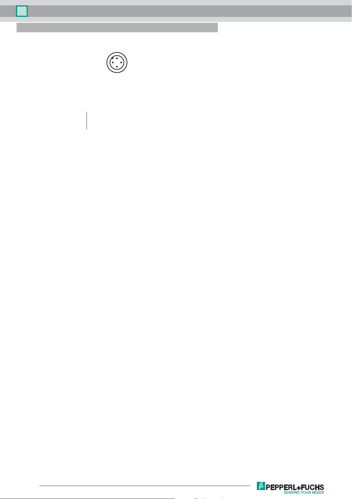
Pinout
1
2
Wire colors in accordance with EN 60947-5-2
1 BN
2 WH
3 BU
4 BK
(brown)
(white)
(blue)
(black)
4
3
Release date: 2012-05-21 11:06 Date of issue: 2016-01-07 126070_eng.xml
Refer to “General Notes Relating to Pepperl+Fuchs Product Information”.
2
 Loading...