

Inductive sensor NCN40-FP-W-T-P1
Technical Data
General specifications
Switching element function AC NO/N C
Model Number
NCN40-FP-W-T-P1
Features
• Temperature range
-25 ... 100 °C (-13 ... 212 °F)
• 40 mm non-flush
Rated operating distance s
Installation non-flush
Output polarity AC
Assured operating distance sa0 ... 32.4 mm
Reduction factor r
Reduction factor rCu 0.3
Reduction factor r
Nominal ratings
Operating voltage UB20 ... 253 V
Switching frequency f 0 ... 20 Hz
Hysteresis H typ. 3 %
Short-circuit protection no
Vol tag e d rop U
Momentary current
(20 ms, 0.1 Hz)
Temperature drift -10 ... 15 % at < -25 °C
S
Operating current I
Off-state current I
Time delay before availability t
Operating voltage indicator LED, green
Switching state indicator LED, yellow
0.4
Al
0.85
304
Ambient conditions
Ambient temperature -25 ... 100 °C (-13 ... 212 °F)
Mechanical specifications
Connection type screw terminals
Information for connection A maximum of two conductors with the same core cross-section
Core cross-section up to 2.5 mm
Minimum core cross-section
Maximum core cross-section
Housing material PBT
Sensing face PBT
Housing base PBT
Degree of protection IP68
Note
Compliance with standards and directives
Stan dard conf ormit y
Sta ndar ds
Approvals and certificates
UL approval cULus Listed, General Purpose
CSA approval cCSAus Listed, General Purpose
CCC approval Certified by China Compulsory Certification (CCC)
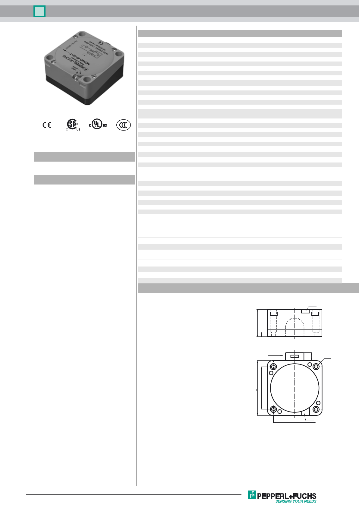
Dimensions
40 mm
n
≤ 5 V typ. 4V
d
≤ 3000 mA
5 ... 500 mA
L
0.3 ... 1 mA typ. 0.7 mA
r
≤ 100 ms
v
may be mounted on one terminal connection!
tightening torque 1.2 Nm + 10 %
without wire end ferrule 0.5 mm
2
2
, with connector sleeves 0.34 mm
without wire end ferrule 2.5 mm2 , with connector sleeves 1.5 mm
1)
In the temperature range below 0 °C, permissible operating volt-
age U
80...253 V
b
Safety fuse ≤ 2 A (quick-blow) according to IEC 60127-2 Sheet 1
Recommendation: after a short circuit, check that the device is
functioning correctly.
EN 60947-5-2:2007
IEC 60947-5-2:2007
2
2
LEDs
40
7
M20 x 1.5
80
65
LEDs
65
Ø5.3
11
Release date: 2016-09-29 11:38 Date of issue: 2016-10-10 130539_eng.xml
Refer to “General Notes Relating to Pepperl+Fuchs Product Information”.
1
Inductive sensor NCN40-FP-W-T-P1
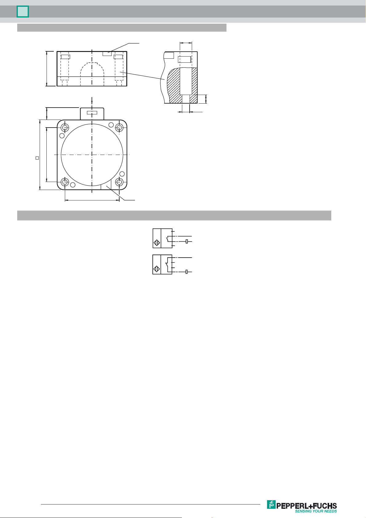
Dimensions
40
11
80
65
Electrical Connection
M20 x 1.5
65
LEDs
LEDs
W, N O
I
W, N C
I
ø 9.5
7
ø 5.3
1
BN
3
4
2
1
3
4
2
L1
N
BU
BN
L1
BU
N
Release date: 2016-09-29 11:38 Date of issue: 2016-10-10 130539_eng.xml
Refer to “General Notes Relating to Pepperl+Fuchs Product Information”.
2
 Loading...