

Pepperl Fuchs NCN3-F31K-N4-K-S Data Sheet
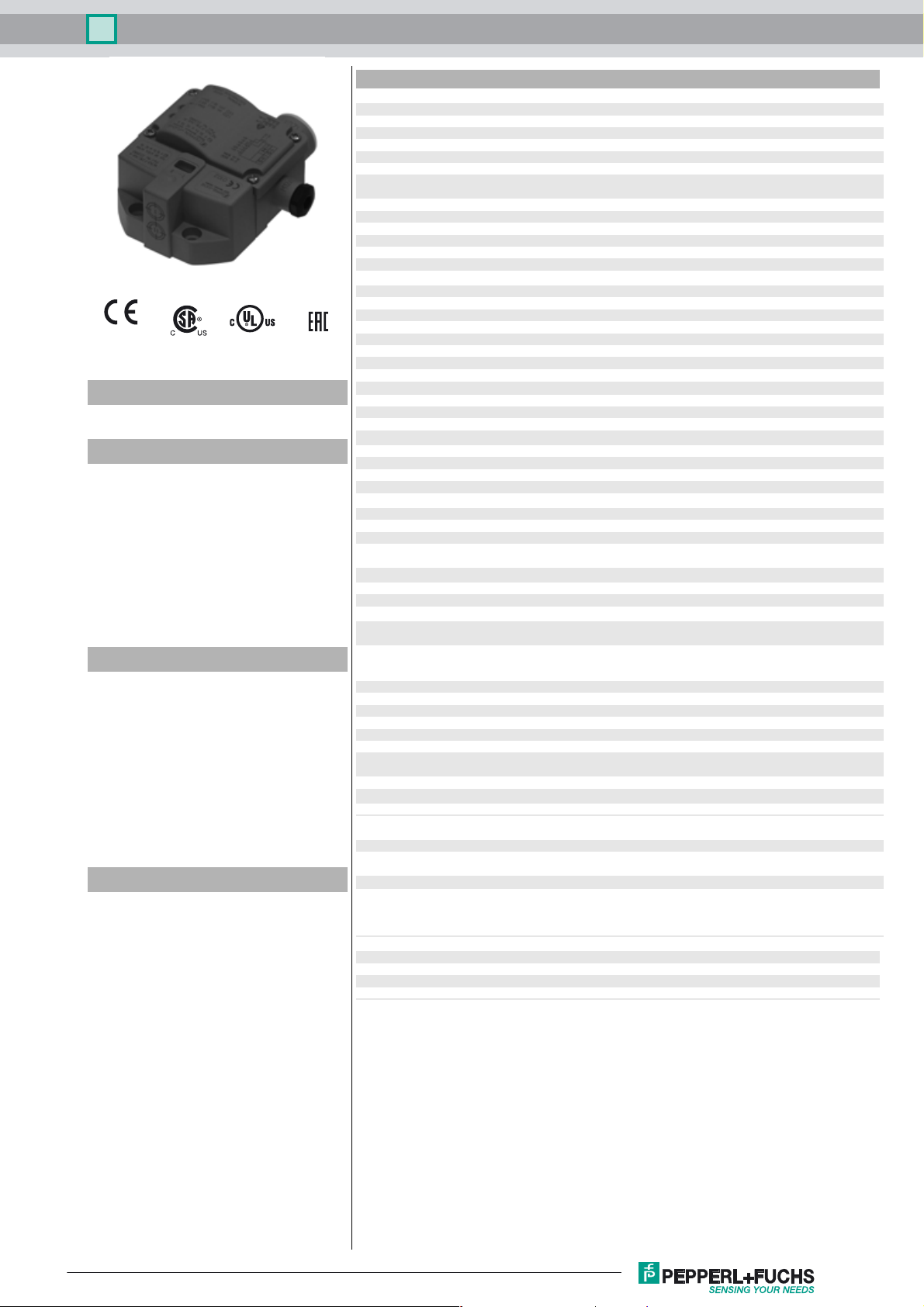
Inductive sensor NCN3-F31K-N4-K-S
Technical Data
General specifications
Switching function 2 x normally closed (NC)
Output type NAMUR
Rated operating distance sn3 mm
Installation flush mountable
Assured operating distance sa0 ... 2.4 mm
0102
Model Number
NCN3-F31K-N4-K-S
Features
• Direct mounting on standard actuators
• Compact and stable housing with
terminal compartment connection
• Fixed setting
• EC-Type Examination Certificate
TÜV99 ATEX 1479X
•Screw terminals
• Usable up to SIL 2 acc. to IEC 61508
• LEDs for switching state of sensor and
solenoid valve
• Valve LEDs disconnectable
Application
Note
The connections to this sensor are sealed
with stopping plugs to protect against dirt and
moisture. If not all of the connections are
used in your application, then seal the remaining stopping plugs on the sensor permanently or check during initial installation and
when performing regular maintenance work
that the stopping plugs are secure and impermeable. If necessary, tighten the stopping
plugs to a torque of 1 Nm.
Accessories
BT65A
Activator for F31 series
BT65X
Activator for F31 series
BT115A
Activator for F31 series
BT115X
Activator for F31 series
BT65B
Activator for F31 series
BT115B
Activator for F31 series
Actual operating distance s
Actuating element Stainless steel 1.4305 / AISI 303
Reduction factor r
Reduction factor rCu 0.4
Reduction factor r
Reduction factor r
Reduction factor r
Output type 2-wire
Nominal ratings
Nominal voltage Uo8 V
Switching frequency f 0 ... 3 kHz
Hysteresis H typ. 5 %
Reverse polarity protection reverse polarity protected
Short-circuit protection yes
Suitable for 2:1 technology yes , Reverse polarity protection diode not required
Current consumption
Measuring plate not detected
Measuring plate detected
Time delay before availability t
Switching state indicator LED, yellow
Valve status indicator LED, yellow
Functional safety related parameters
Safety Integrity Level (SIL) SIL 2
MTTFd 1470 a
Mission Time (T
Diagnostic Coverage (DC) 0 %
Valve circuit
Voltage max. 32 V DC
Current max. 240 mA
Short-circuit protection no
Reverse polarity protection yes, with reversed output LED is out of function, therfore more
Ambient conditions
Ambient temperature -25 ... 100 °C (-13 ... 212 °F)
Storage temperature -40 ... 100 °C (-40 ... 212 °F)
Mechanical specifications
Connection (system side) Screw terminals, tightening torque min. 0.5 Nm
Core cross-section (system side) rigid: 0.14 ... 2.5 mm
Connection (valve side) like connection (system side)
Core cross-section (valve side) like core cross section (system side)
Housing material PBT
Sensing face PBT
Degree of protection IP67
Tightening torque, housing screws 1 Nm
Tightening torque, cable gland M20 x 1.5 ; ≤ 7 Nm
Note LED switch-off
General information
Use in the hazardous area see instruction manuals
Compliance with standards and
directives
Standard conformity
NAMUR
Electromagnetic compatibility
Standards
Approvals and certificates
EAC conformity TR CU 012/2011
UL approval cULus Listed, General Purpose
CSA approval cCSAus Listed, General Purpose
CCC approval CCC approval / marking not required for products rated ≤36 V
0.5
Al
1
304
1.3
St37
0.6
Brass
) 20 a
M
2.7 ... 3.3 mm typ.
r
8.5 mm x 8.5 mm x 0.5 mm
≥ 3 mA
≤ 1 mA
≤ 1.1 ms
v
power for solenoid valve
Stripped length 7 mm
flexible: 0.14 ... 1.5 mm
flexible with core-end sleeve: 0.25 ... 1.5 mm
M12 x 1.5 ; ≤ 3 Nm
EN 60947-5-6:2000
IEC 60947-5-6:1999
NE 21:2007
EN 60947-5-2:2007
EN 60947-5-2/A1:2012
IEC 60947-5-2:2007
IEC 60947-5-2 AMD 1:2012
2
2
2
Release date: 2018-04-19 08:15 Date of issue: 2018-04-19 222681_eng.xml
Refer to “General Notes Relating to Pepperl+Fuchs Product Information”.
1

Inductive sensor NCN3-F31K-N4-K-S
Dimensions
65
I
40
35
95
9
II
14 11
5.4
M20 x 1.5
S
M12 x 1.5
77.5
LED
7
Electrical Connection
N4-K
I
I
II
S
V
V
LED
30
I
II
4
5
1
2
9 / 10
10 / 9
7 / 6
6 / 7
L+
LL+
L-
(V-)
V+
(V+)
V-
(V+)
VV+
(V-)
Interruption of LED:
In the case of a polarity reversal of the
valve circuit connection/s, the valve
status display does not function, i.e.
such that low power valves can (also) be
connected.
Release date: 2018-04-19 08:15 Date of issue: 2018-04-19 222681_eng.xml
Refer to “General Notes Relating to Pepperl+Fuchs Product Information”.
2
 Loading...