


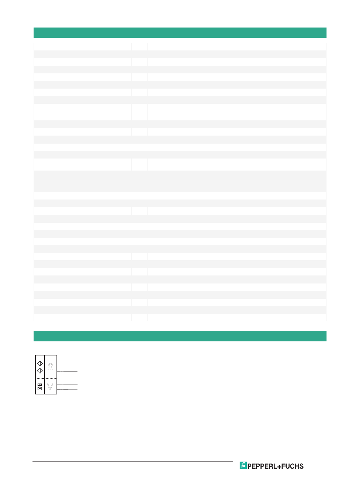
Inductive sensor
Sensor 2
Sensor 1
Drawing without actuator
5.4
7
36
30
65
14
25
33.5
5
M12x1
Germany: +49 621 776 1111Pepperl+Fuchs Group
Refer to "General Notes Relating to Pepperl+Fuchs Product Information".
USA: +1 330 486 0001 Singapore: +65 6779 9091
www.pepperl-fuchs.com fa-info@us.pepperl-fuchs.com fa-info@sg.pepperl-fuchs.com
fa-info@de.pepperl-fuchs.com
NCN3-F31-B3B-V1-K
Direct mounting on standard actuators
<
A/B slave with extended addressing possibility for up to 62 slaves
<
Mode of operation, programmable
<
Degree of protection IP67
<
Communication monitoring, turn-off
<
Lead breakage and short-circuit monitoring of the valve
<
Valve positioner and valve control module
Dimensions
Technical Data
General specifications
Switching function Normally open/closed (NO/NC) programmable
Output type AS-Interface
Rated operating distance s
Installation flush mountable
Assured operating distance s
Reduction factor rAl 0.5
Reduction factor rCu 0.45
Reduction factor r
Reduction factor r
Slave type A/B slave
AS-Interface specification V3.0
Required master specification ≥ V2.1
Nominal ratings
Operating voltage U
Switching frequency f 0 ... 100 Hz
Release date: 2020-03-23 Date of issue: 2020-03-30 Filename: 226322_eng.pdf
1
304
1.2
St37
3 mm
n
0 ... 2.43 mm
a
26.5 ... 31.9 V via AS-i bus system
B
1
+
V+
1
B3B-V1-K
A S-I
-
V-
3
2 / RD
4 / YE
I
I
II
S
V
2
Inductive sensor NCN3-F31-B3B-V1-K
Germany: +49 621 776 1111Pepperl+Fuchs Group
Refer to "General Notes Relating to Pepperl+Fuchs Product Information".
USA: +1 330 486 0001 Singapore: +65 6779 9091
www.pepperl-fuchs.com fa-info@us.pepperl-fuchs.com fa-info@sg.pepperl-fuchs.com
fa-info@de.pepperl-fuchs.com
Technical Data
No-load supply current I
≤ 35 mA
0
Functional safety related parameters
MTTF
d
842 a
Mission Time (TM) 20 a
Diagnostic Coverage (DC) 0 %
Indicators/operating means
LED PWR AS-Interface voltage; LED green
LED IN switching state (input); LED yellow
LED OUT binary LED yellow/red
yellow: switching state
red: lead breakage/short-circuit
Electrical specifications
Rated operating voltage U
Rated operating current I
26.5 ... 31.6 V from AS-Interface
e
100 mA
e
Compliance with standards and directives
Standard conformity
Electromagnetic compatibility EN 50295:1999-10
Standards EN 60947-5-2:2007
EN 60947-5-2/A1:2012
IEC 60947-5-2:2007
IEC 60947-5-2 AMD 1:2012
Approvals and certificates
UL approval cULus Listed, General Purpose
CSA approval cCSAus Listed, General Purpose
CCC approval CCC approval / marking not required for products rated ≤36 V
Ambient conditions
Ambient temperature -25 ... 70 °C (-13 ... 158 °F)
Mechanical specifications
Connection (system side) 4-pin, M12 x 1 connector
Connection (valve side) 0.5 m, PVC cable
Core cross-section (valve side) 0.75 mm
2
Connector housing metal
Housing material PBT
Degree of protection IP67
Cable
Cable diameter 6 mm ± 0.2 mm
Bending radius > 10 x cable diameter
Note valve voltage limited to 26,4 V max.; valve power 2,5 W max.
Connection
Release date: 2020-03-23 Date of issue: 2020-03-30 Filename: 226322_eng.pdf
2

1
3
4
2
Val ve connection
AS-Interface
LED OUT
IN 2 PWR IN 1
AS-Interface
Inductive sensor NCN3-F31-B3B-V1-K
Germany: +49 621 776 1111Pepperl+Fuchs Group
Refer to "General Notes Relating to Pepperl+Fuchs Product Information".
USA: +1 330 486 0001 Singapore: +65 6779 9091
www.pepperl-fuchs.com fa-info@us.pepperl-fuchs.com fa-info@sg.pepperl-fuchs.com
fa-info@de.pepperl-fuchs.com
Connection Assignment
Assembly
Release date: 2020-03-23 Date of issue: 2020-03-30 Filename: 226322_eng.pdf
3

Programming Instructions
Address 00 preset, alterable via Busmaster
or progrmming units
IO-code D
ID-code A
ID1-code 7
ID2-code E
Data bit
Bit Function
D0 valve status
(0=valve OFF, 1=valve ON)
D1 valve fault
1)
(0=lead breakage/short circuit;
1=no fault)
D2 switch output sensor 1
2)
(0=damped; 1=undamped)
D3 switch output sensor 2
2)
(0=damped; 1=undamped)
Parameter bit
Bit Function
P0 Watchdog (0=inactive; 1=active)
3)
P1 switching element function sensor II
4)
0=NO; 1= NC)
P2 switching element function sensor I
4)
0=NO; 1= NC)
P3 not used
1)
Verification only with actuated valve (D0=1)
2)
Applies to NC function (P1/P2=1; preset), with NO
function (P1/P2=0) reversed characteristics
3)
Watchdog active: valve voltage drops with the
occurrence of an AS-I communication fault
Val ve
connection
+ red
- yellow
Sensor I
Sensor II
+
-
1
3
AS-Interface +
AS-Interface -
Inductive sensor NCN3-F31-B3B-V1-K
Germany: +49 621 776 1111Pepperl+Fuchs Group
Refer to "General Notes Relating to Pepperl+Fuchs Product Information".
USA: +1 330 486 0001 Singapore: +65 6779 9091
www.pepperl-fuchs.com fa-info@us.pepperl-fuchs.com fa-info@sg.pepperl-fuchs.com
fa-info@de.pepperl-fuchs.com
Additional Information
Connection
Release date: 2020-03-23 Date of issue: 2020-03-30 Filename: 226322_eng.pdf
4

Inductive sensor NCN3-F31-B3B-V1-K
Germany: +49 621 776 1111Pepperl+Fuchs Group
Refer to "General Notes Relating to Pepperl+Fuchs Product Information".
USA: +1 330 486 0001 Singapore: +65 6779 9091
www.pepperl-fuchs.com fa-info@us.pepperl-fuchs.com fa-info@sg.pepperl-fuchs.com
fa-info@de.pepperl-fuchs.com
Matching system components
BT115A Activator for F31 series
BT115X Activator for F31 series
Accessories
BT65B Activator for F31 series
BT115B Activator for F31 series
V1-W-2M-PUR Female cordset, M12, 4-pin, PUR cable
V1-G-2M-PUR Female cordset, M12, 4-pin, PUR cable
BT65A Activator for F31 series
BT65X Activator for F31 series
Release date: 2020-03-23 Date of issue: 2020-03-30 Filename: 226322_eng.pdf
5

Germany: +49 621 776 1111Pepperl+Fuchs Group
Refer to "General Notes Relating to Pepperl+Fuchs Product Information".
USA: +1 330 486 0001 Singapore: +65 6779 9091
www.pepperl-fuchs.com fa-info@us.pepperl-fuchs.com fa-info@sg.pepperl-fuchs.com
fa-info@de.pepperl-fuchs.com
Inductive sensor
NCN3-F31-B3B-V1-K
Function
The NCN3-F31-B3B-V1-K is an inductive dual sensor used to indicate the valve positioning of actuators. The dual sensor is
mounted directly on the actuator using two screws. Additional adjustment is not necessary.
A cable connection on the sensor is used directly for the valve controls. The NCN3-F31-B3B-V1-K is connected via a M12x1
screw fixing to the bus line. This makes it possible to transmit both the switch signal for the valve and the messages of the sensors
via AS-Interface. They are both powered directly through the bus cable. Moreover, the valve is monitored for lead breakage and
short circuit. The D1 data bit monitors the fault signal.
The sensors can be programmed as normally closed and normally open contacts (parameter bit P1 and P2). If there are no
communications on the bus cable, the valve is automatically de-energised. This communication monitoring can be turned off via
the parameter bit P0.
The current switching states are displayed by means of yellow LEDs.
Release date: 2020-03-23 Date of issue: 2020-03-30 Filename: 226322_eng.pdf
6
 Loading...