

Inductive sensor NCN12-18GM50-Z4-V1
Technical Data
General specifications
Switching element function DC NO
Model Number
NCN12-18GM50-Z4-V1
Features
• 12 mm non-flush
•2-wire DC
• Increased operating distance
Accessories
BF 18
Mounting flange, 18 mm
V1-G
Female connector, M12, 4-pin, field attachable
V1-W
Female connector, M12, 4-pin, field attachable
V1-G-2M-PUR
Female cordset, M12, 4-pin, PUR cable
V1-W-2M-PUR
Female cordset, M12, 4-pin, PUR cable
Rated operating distance s
Installation non-flush
Output polarity DC
Assured operating distance sa0 ... 9.1 mm
Reduction factor r
Reduction factor rCu 0.45
Reduction factor r
Reduction factor r
Nominal ratings
Operating voltage UB3.5 ... 30 V
Switching frequency f 0 ... 1000 Hz
Hysteresis H typ. 3 %
Reverse polarity protection reverse polarity-conductive
Short-circuit protection pulsing
Vol tag e d rop U
Temperature drift ± 15%
Operating current I
Off-state current I
Switching state indicator LED, yellow
Pre-fault indicator LED, red
Stability control-switch point 0,8 s
Ambient conditions
Ambient temperature -25 ... 70 °C (-13 ... 158 °F)
Storage temperature -25 ... 85 °C (-13 ... 185 °F)
Mechanical specifications
Connection type Connector M12 x 1 , 4-pin
Housing material brass, nickel-plated
Sensing face PBT
Degree of protection IP67
Compliance with standards and directives
Stan dard conf ormit y
Sta ndar ds
Approvals and certificates
UL approval cULus Listed, General Purpose
CSA approval cCSAus Listed, General Purpose
CCC approval CCC approval / marking not required for products rated ≤36 V
0.5
Al
0.75
304
0.55
Brass
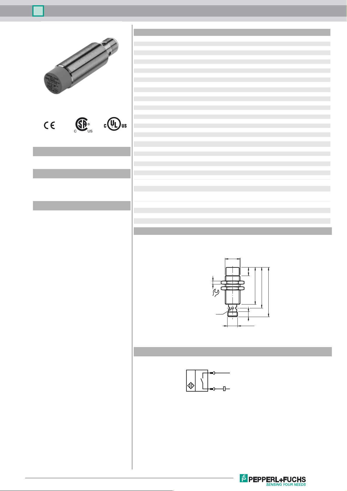
Dimensions
12 mm
n
≤ 3.5 V
d
2 ... 100 mA
L
typ. 0.8 mA
r
EN 60947-5-2:2007
IEC 60947-5-2:2007
... 0,9 s
r
M18 x 1
r
Electrical Connection
10
4
24
LED
45
50
60
6
M12 x 1
1
4
L+
L-
Release date: 2014-12-08 14:10 Date of issue: 2014-12-08 128873_eng.xml
Refer to “General Notes Relating to Pepperl+Fuchs Product Information”.
1
Inductive sensor NCN12-18GM50-Z4-V1
Pinout
1
Installation Hint
2
Wire colors in accordance with EN 60947-5-2
1 BN
2 WH
3 BU
4 BK
(brown)
(white)
(blue)
(black)
4
3
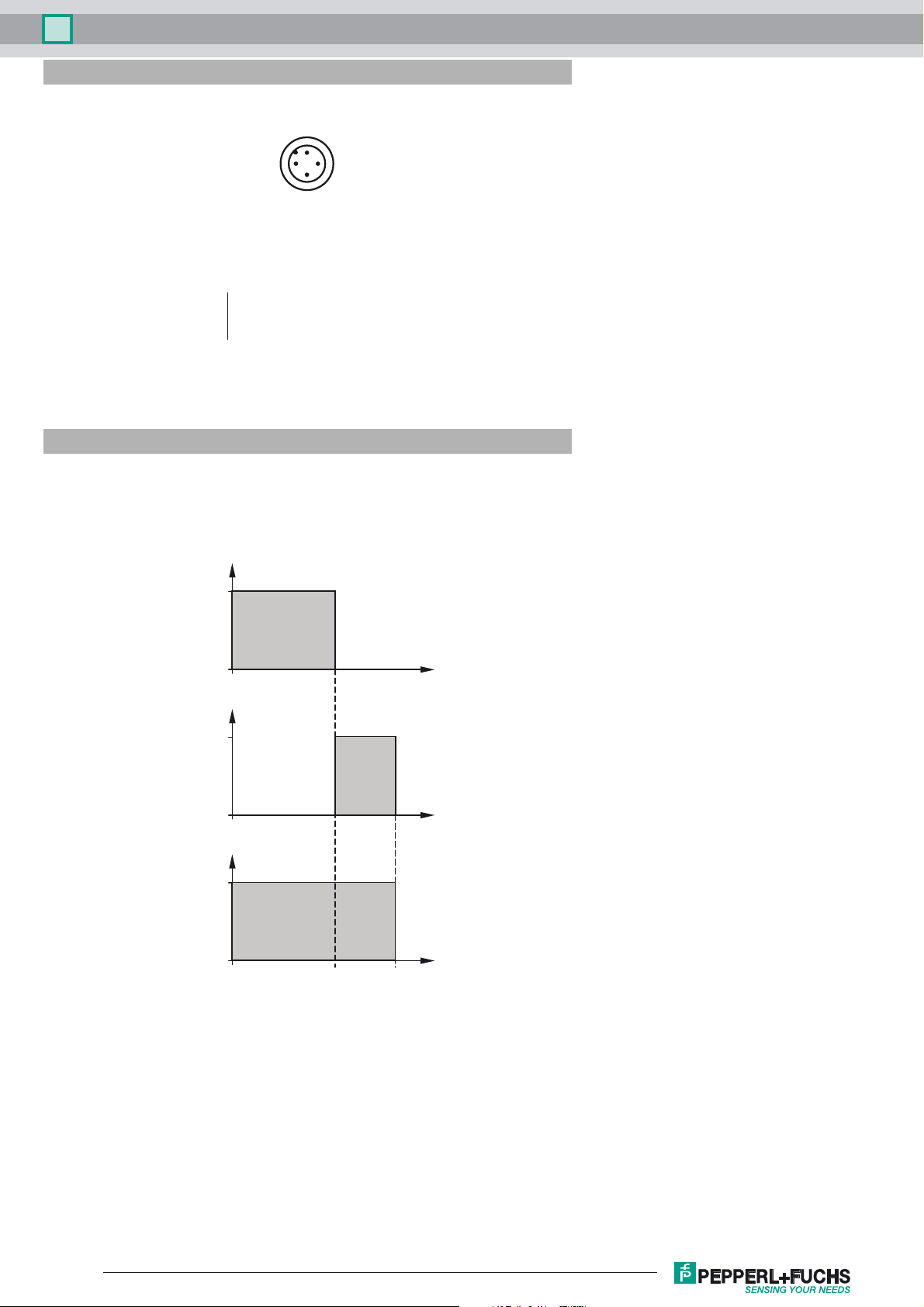
Correlation between output signal/LED-
function and stable operating distance s
effective operating distance
(s
typ. 80 % of sr)
s
LED yellow
sr:
1
/
s
LED red
Output
1
1
S
s
S
r
Release date: 2014-12-08 14:10 Date of issue: 2014-12-08 128873_eng.xml
Refer to “General Notes Relating to Pepperl+Fuchs Product Information”.
2
 Loading...