

Pepperl Fuchs NCN12-18GM50-Z4 Data Sheet
Inductive sensor NCN12-18GM50-Z4
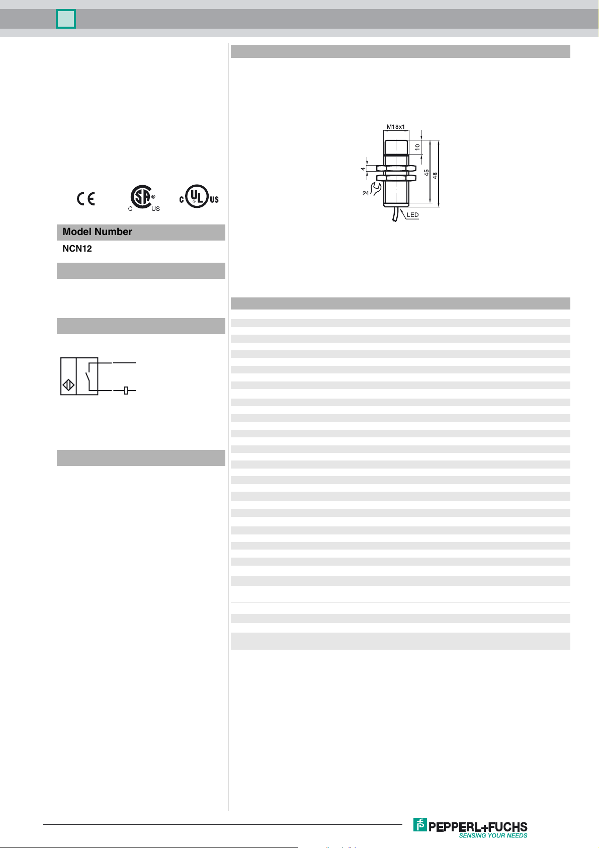
Dimensions
M18x1
10
Model Number
NCN12-18GM50-Z4
Features
• 12 mm not embeddable
•2-wire DC
• Increased operating distance
Connection
BN
BU
L+
L-
Accessories
BF 18
Mounting flange, 18 mm
4
24
LED
45
48
Technical Data
General specifications
Switching element function DC NO
Rated operating distance s
Installation not embeddable
Output polarity DC
Assured operating distance sa0 ... 9.1 mm
Reduction factor r
Reduction factor rCu 0.45
Reduction factor r
Reduction factor r
Nominal ratings
Operating voltage UB3.5 ... 30 V
Switching frequency f 0 ... 1000 Hz
Hysteresis H typ. 3 %
Reverse polarity protected reverse polarity-conductive
Short-circuit protection pulsing
Voltage drop U
Temperature drift ± 15%
Operating current I
Off-state current I
Indication of the switching state LED, yellow
Pre-fault indication LED, red
Stability control-switch point 0,8 s
Ambient conditions
Ambient temperature -25 ... 70 °C (-13 ... 158 °F)
Storage temperature -25 ... 85 °C (-13 ... 185 °F)
Mechanical specifications
Connection type cable PVC , 2 m
Core cross-section 0.34 mm
Housing material brass, nickel-plated
Sensing face PBT
Protection degree IP67
Compliance with standards and directives
Standard conformity
Standards
Approvals and certificates
UL approval cULus Listed, General Purpose
CSA approval cCSAus Listed, General Purpose
CCC approval Products with a maximum operating voltage of ≤36 V do not bear a
0.5
Al
0.75
303
0.55
Brass
12 mm
n
≤ 3.5 V
d
2 ... 100 mA
L
typ. 0.8 mA
r
... 0,9 s
r
r
2
EN 60947-5-2:2007
IEC 60947-5-2:2007
CCC marking because they do not require approval.
Release date: 2011-07-14 07:41 Date of issue: 2011-07-14 112947_eng.xml
Subject to modifications without notice
Copyright Pepperl+Fuchs
1
Inductive sensor NCN12-18GM50-Z4
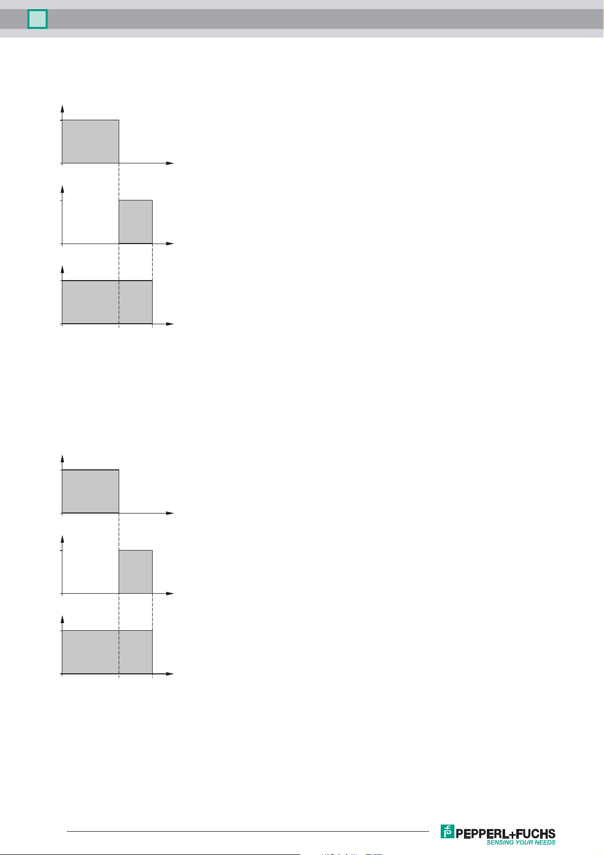
Correlation between output signal/LED-
function and stable operating distance s
effective operating distance
(s
typ. 80 % of sr)
s
LED yellow
sr:
1
LED red
1
Output
1
/
s
S
s
Correlation between output signal/LED-
function and stable operating distance s
effective operating distance
(s
typ. 80 % of sr)
s
LED yellow
sr:
1
LED red
1
Output
1
S
r
/
s
S
Subject to modifications without notice
S
s
r
Release date: 2011-07-14 07:41 Date of issue: 2011-07-14 112947_eng.xml
Copyright Pepperl+Fuchs
2
 Loading...