

Pepperl Fuchs NCB5-18GM40-Z0-V1-3G-3D Data Sheet
Inductive sensor NCB5-18GM40-Z0-V1-3G-3D
Technical Data
General specifications
Switching function Normally open (NO)
Output type Two-wire
Rated operating distance sn5 mm
Installation flush
Output polarity DC
Model Number
NCB5-18GM40-Z0-V1-3G-3D
Features
• Comfort series
•5 mm flush
• ATEX-approval for zone 2 and zone 22
Accessories
EXG-18
Quick mounting bracket with dead stop
BF 18
Mounting flange, 18 mm
Assured operating distance s
Actual operating distance sr4.5 ... 5.5 mm typ. 5 mm
Reduction factor r
Reduction factor rCu 0.33
Reduction factor r
Output type 2-wire
Nominal ratings
Operating voltage UB5 ... 60 V
Switching frequency f 0 ... 350 Hz
Hysteresis H 1 ... 15 typ. 5 %
Reverse polarity protection reverse polarity tolerant
Short-circuit protection pulsing
S
Voltage drop U
Voltage drop at IL
Voltage drop I
element on U
Operating current I
Off-state current I
Time delay before availability t
Switching state indicator Multihole-LED, yellow
Functional safety related parameters
MTTFd 1739 a
Mission Time (TM) 20 a
Diagnostic Coverage (DC) 0 %
Ambient conditions
Ambient temperature -25 ... 70 °C (-13 ... 158 °F)
Mechanical specifications
Connection type Connector plug M12 x 1 , 4-pin
Housing material Stainless steel 1.4305 / AISI 303
Sensing face PBT
Degree of protection IP67
General information
Use in the hazardous area see instruction manuals
Category
Compliance with standards and
directives
Standard conformity
Standards
Approvals and certificates
UL approval cULus Listed, General Purpose
CSA approval cCSAus Listed, General Purpose
CCC approval Certified by China Compulsory Certification (CCC)
Al
304
= 20 mA, switching
L
d
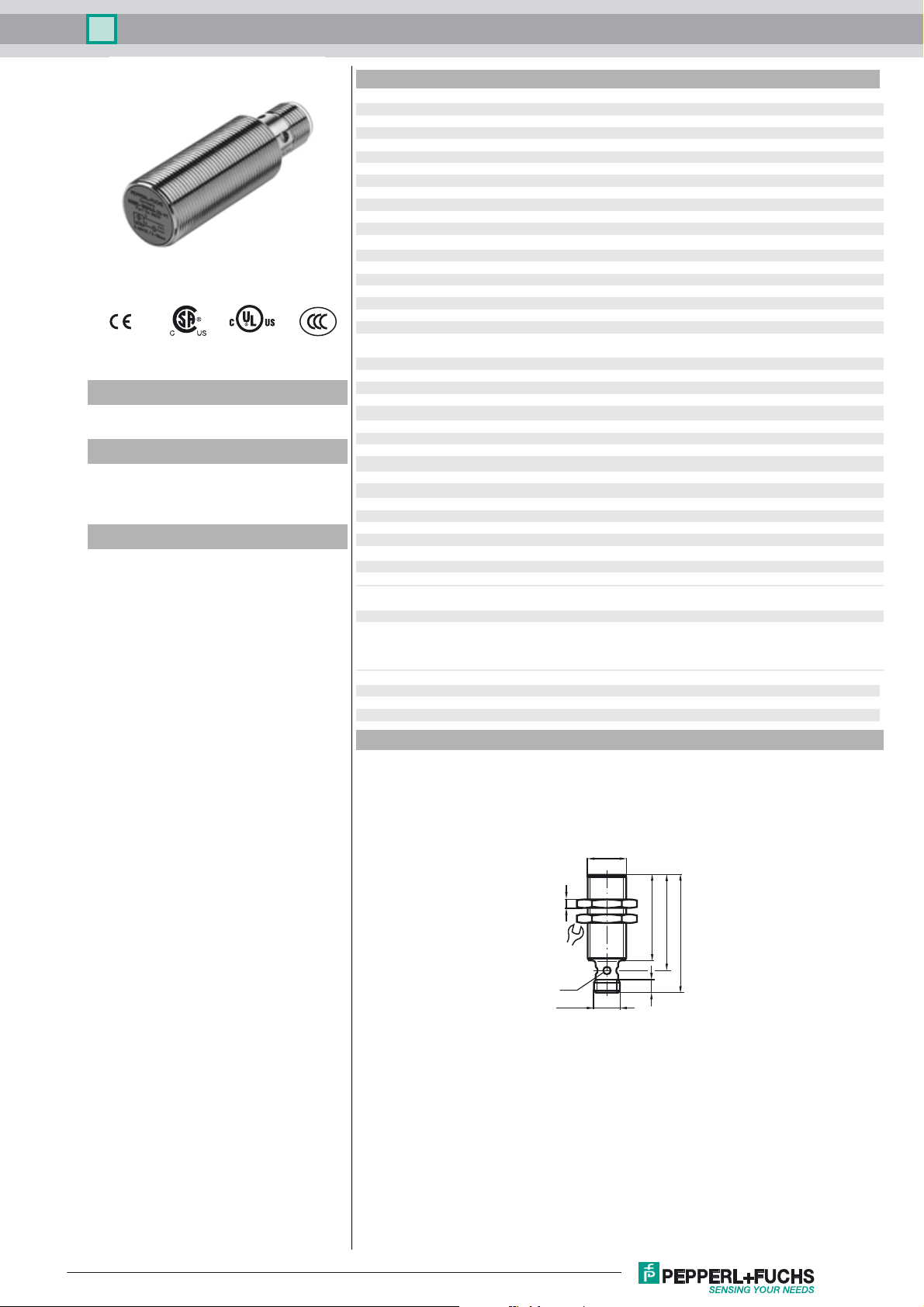
Dimensions
0.37
0.7
0 ... 4.05 mm
a
≤ 5 V
d
3.4 ... 5 V typ. 4.3 V
2 ... 100 mA
L
0 ... 0.5 mA typ.
r
≤ 20 ms
v
3G; 3D
EN 60947-5-2:2007
EN 60947-5-2/A1:2012
IEC 60947-5-2:2007
IEC 60947-5-2 AMD 1:2012
Release date: 2018-02-28 07:18 Date of issue: 2018-02-28 211267_eng.xml
Refer to “General Notes Relating to Pepperl+Fuchs Product Information”.
4
24
LED
M12x1
M18x1
40
45
55
6
1
Inductive sensor NCB5-18GM40-Z0-V1-3G-3D
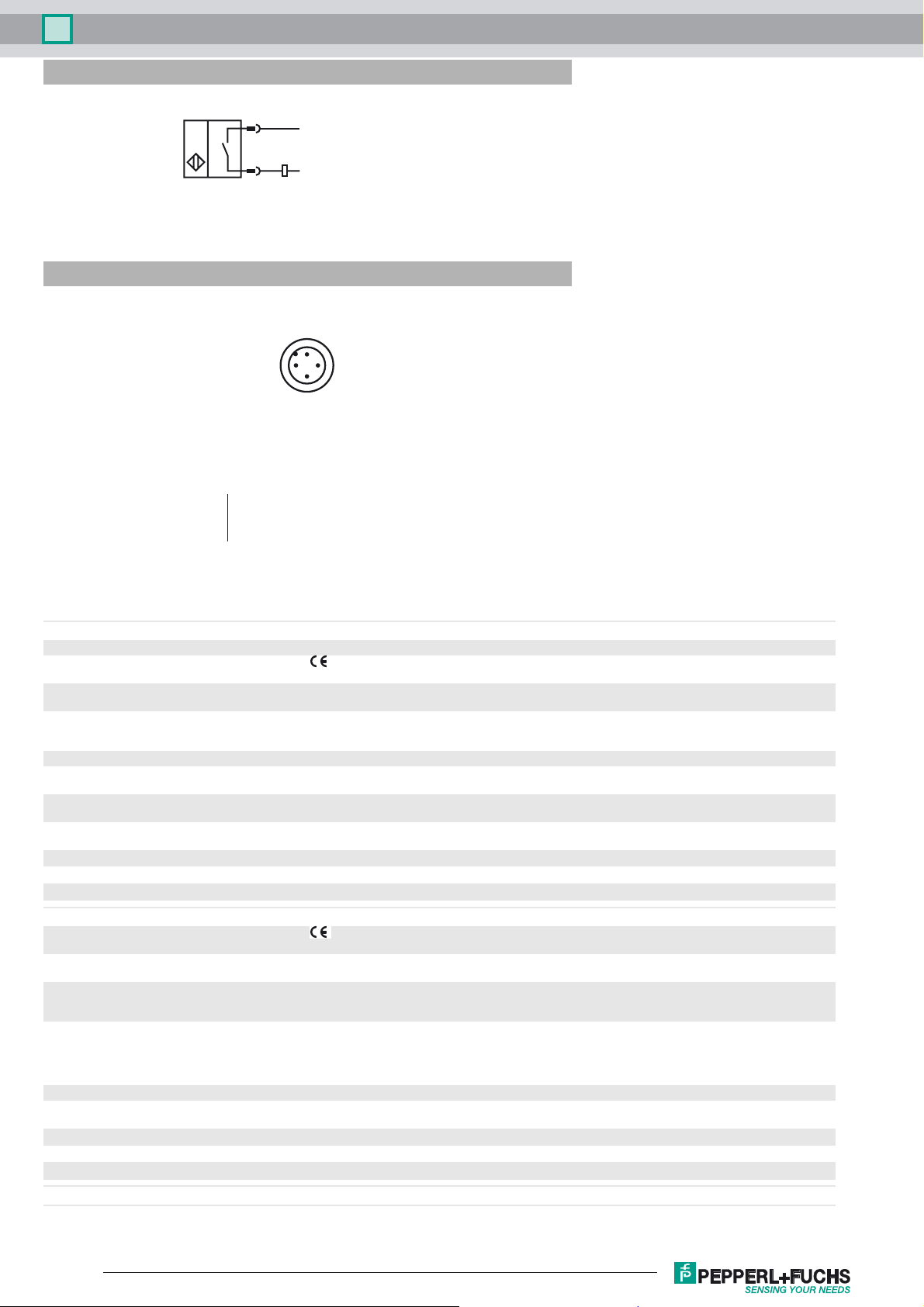
Electrical Connection
Pinout
3
4
L+
L-
1
2
4
3
Wire colors in accordance with EN 60947-5-2
1 BN
2 WH
3 BU
4 BK
(brown)
(white)
(blue)
(black)
Equipment protection level Gc (nA)
Certificate PF 15CERT3754 X
CE marking
ATEX marking ¬ II 3G Ex nA IIC T6 Gc
Standards EN 60079-0:2012+A11:2013, EN 60079-15:2010
Special conditions
Maximum operating current I
Maximum operating voltage U
Maximum permissible ambient temperature T
at U
at U
at U
Equipment protection level Dc (tc)
CE marking
ATEX marking ¬ II 3D Ex tc IIIC T80°C Dc
Standards EN 60079-0:2012+A11:2013, EN 60079-31:2014
General The corresponding datasheets, declarations of conformity, EC-type examination certificates, certifications, and
Special conditions
Maximum permissible ambient temperature T
at U
at U
at U
Equipment protection level Dc (tD)
=60 V, IL=100 mA
Bmax
=60 V, IL=50 mA
Bmax
=60 V, IL=25 mA
Bmax
=60 V, IL=100 mA
Bmax
=60 V, IL=50 mA
Bmax
=60 V, IL=25 mA
Bmax
L
Bmax
The Ex-related marking can also be printed on the enclosed label.
Ignition protection category "n"
Use is restricted to the following stated conditions
The maximum permissible load current must be restricted to the values given in the following list. High load currents
and load short-circuits are not permitted.
The maximum permissible operating voltage UB max is restricted to the values in the following list. Tolerances are
not permissible.
dependant of the load current I
Umax
Information can be taken from the following list.
51 °C (123.8 °F)
57 °C (134.6 °F)
60 °C (140 °F)
The Ex-related marking can also be printed on the enclosed label.
Protection by enclosure "tc" Some of the information in this instruction manual is more specific than the information
provided in the datasheet.
control draw see datasheets), form an integral part of this document. These documents can
be found at The maximum surface temperature of the device was determined without a
layer of dust of the information in this instruction manual is more specific than the
information provided in the datasheet.
dependant of the load current I
Umax
Information can be taken from the following list.
51 °C (123.8 °F)
57 °C (134.6 °F)
60 °C (140 °F)
and the max. operating voltage U
L
and the max. operating voltage U
L
Bmax
Bmax
Release date: 2018-02-28 07:18 Date of issue: 2018-02-28 211267_eng.xml
Refer to “General Notes Relating to Pepperl+Fuchs Product Information”.
2
 Loading...