

Inductive sensor NCB4-12GM70-E2-M
Technical Data
General specifications
Switching element function PNP NO
Model Number
NCB4-12GM70-E2-M
Features
•Comfort series
•4 mm flush
• Increased operating distance
• Extended temperature range 40 ... +85 °C
• E1-Type approval
• Increased noise immunity 100 V/m
Accessories
BF 12
Mounting flange, 12 mm
E 1
Rated operating distance s
Installation flush
Output polarity DC
Assured operating distance sa0 ... 3.24 mm
Reduction factor r
Reduction factor rCu 0.4
Reduction factor r
Nominal ratings
Operating voltage UB10 ... 60 V
Switching frequency f 0 ... 1000 Hz
Hysteresis H typ. 5 %
Reverse polarity protection reverse polarity protected
Short-circuit protection pulsing
Vol tag e d rop Ud≤ 3 V
Rated insulation voltage U
Operating current I
Off-state current I
No-load supply current I
Time delay before availability t
Switching state indicator LED, yellow
Functional safety related parameters
MTTFd 1050 a
Mission Time (T
Diagnostic Coverage (DC) 0 %
Ambient conditions
Ambient temperature -40 ... 85 °C (-40 ... 185 °F)
Mechanical specifications
Connection type cable PUR , 2 m
Core cross-section 0.75 mm
Housing material Stainless steel 1.4305 / AISI 303
Sensing face PBT
Degree of protection IP69K
Mass 120 g
Compliance with standards and directives
Stan dard conf ormit y
Sta ndar ds
Approvals and certificates
Protection class II
Rated insulation voltage U
Design-impulse-voltage withstan d U
UL approval cULus Listed, General Purpose
CSA approval cCSAus Listed, General Purpose
E1 Type approval 10R-04
0.45
Al
0.75
304
) 20 a
M
4 mm
n
60 V
BIS
0 ... 200 mA
L
0 ... 0.5 mA typ. 0.1 µA
r
≤ 10 mA
0
≤ 5 ms
v
EN 60947-5-2:2007
IEC 60947-5-2:2007
60 V
i
800 V
imp
2
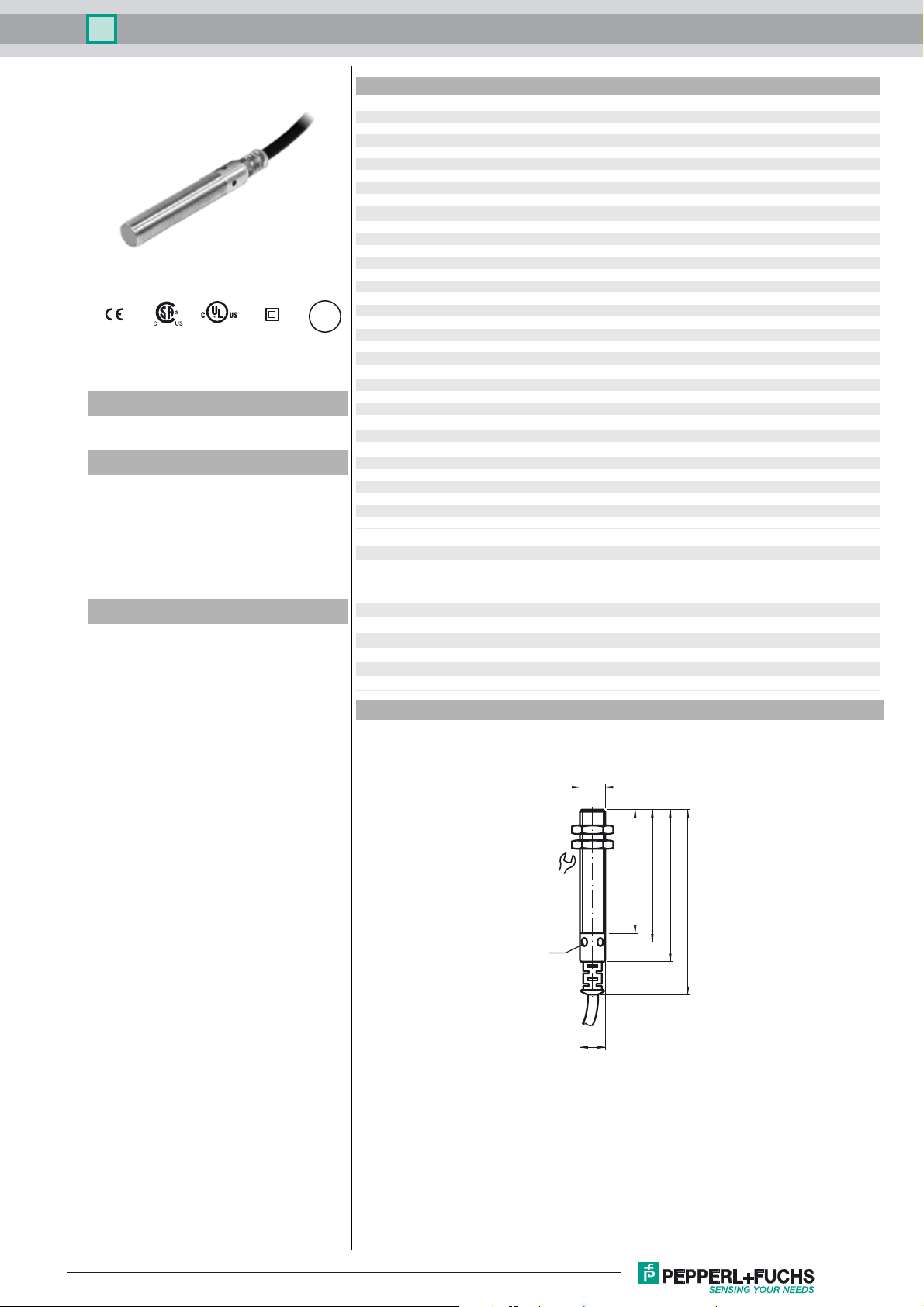
Dimensions
17
LED
M12 x 1
ø 12
55
60
70
86
Release date: 2014-10-30 11:45 Date of issue: 2014-10-30 180332_eng.xml
Refer to “General Notes Relating to Pepperl+Fuchs Product Information”.
1
Inductive sensor NCB4-12GM70-E2-M
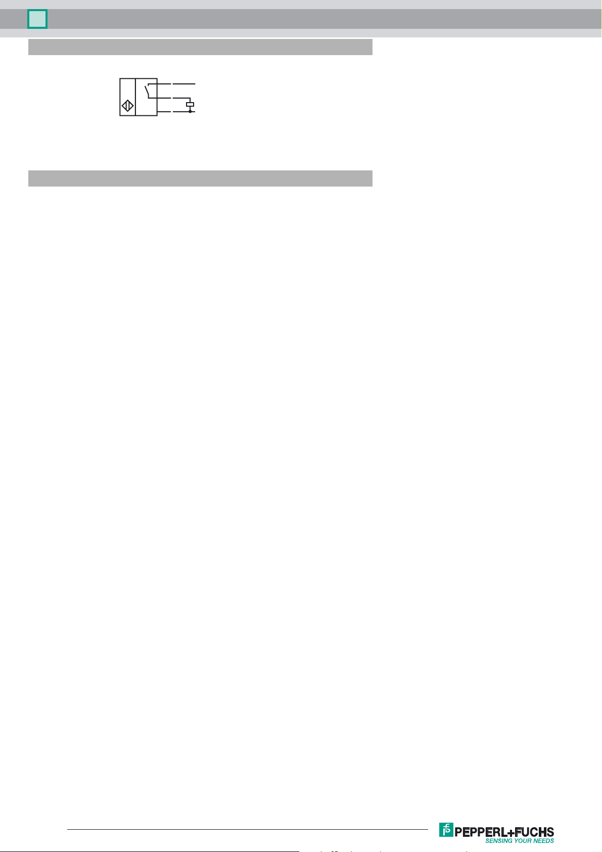
Electrical Connection
Installation Hint
BN
BK
BU
Emitted interference and interference
immunity in accordance with motor vehicle
directive 2006/28/EG (e1 Type approval)
Interference immunity in accordance with DIN
ISO 11452-2:
Severity IV 100 V/m
Frequency band 200 MHz up to 2 GHz
Interference immunity to DIN ISO 11452-3:
Severity IV 200 V/m
Frequency band 0.15 MHz to 200 MHz
Mains-borne interference in accordance with
ISO 7637-2:
Pulse 1 2a 2b 3a 3 b 4 5
Severity level IV IV IV IV IV IV IV
Failure criterion C A C A A A C
EN 61000-4-2: CD: 8 kV / AD: 15 kV
Severity level IV IV
EN 61000-4-3: 10 V/m (80...1000 MHz)
Severity level III
EN 61000-4-4: 2 kV
Severity level III
EN 61000-4-5: Supply line to line 0.5 kV
Severity level I
EN 61000-4-6: 10 V (0.15...80 MHz)
Severity level III
EN 55011: Class B
L+
L-
Release date: 2014-10-30 11:45 Date of issue: 2014-10-30 180332_eng.xml
Refer to “General Notes Relating to Pepperl+Fuchs Product Information”.
2
 Loading...