

Inductive sensor NCB40-FP-W-P2
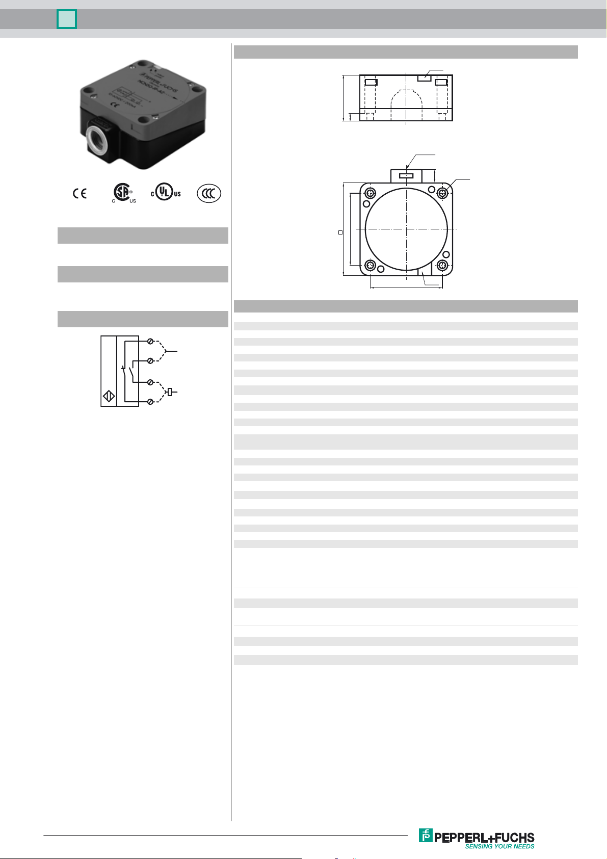
Dimensions
LEDs
40
7
1/2" NPT
ø 5.3
11
S
80
Model Number
NCB40-FP-W-P2
65
Features
• Comfort series
• 40 mm embeddable
Connection
1
3
4
2
LEDs
65
Technical Data
General specifications
Switching element function AC NO/NC
Rated operating distance s
Installation embeddable
L
N
Output polarity AC
Assured operating distance sa0 ... 32.4 mm
Reduction factor r
Reduction factor rCu 0.23
Reduction factor r
Nominal ratings
Operating voltage UB20 ... 253 V
Switching frequency f 0 ... 20 Hz
Hysteresis H typ. 3 %
Short-circuit protection no
Voltage drop U
Momentary current
(20 ms, 0.1 Hz)
Operating current I
Off-state current I
Operating voltage display LED, green
Indication of the switching state LED, yellow
0.25
Al
0.85
V2A
Ambient conditions
Ambient temperature -25 ... 70 °C (-13 ... 158 °F)
Mechanical specifications
Connection type screw terminals
Core cross-section up to 2.5 mm
Housing material PBT
Sensing face PBT
Protection degree IP68
Note
Compliance with standards and directives
Standard conformity
tandards
S
Approvals and certificates
UL approval cULus Listed, General Purpose
CSA approval cCSAus Listed, General Purpose
CCC approval Certified by China Compulsory Certification (CCC)
40 mm
n
≤ 5 V typ. 4V
d
≤ 4000 mA
5 ... 500 mA
L
0.3 ... 1 mA typ. 0.7 mA
r
2
1)
In the temperature range below 0 °C, permissible operating vol-
tage U
80...253 V
b
Safety fuse ≤ 2 A (quick-blow) according to IEC 60127-2 Sheet 1
Recommendation: after a short circuit, check that the device is
functioning correctly.
EN 60947-5-2:2007
IEC 60947-5-2:2007
Release date: 2010-11-20 15:54 Date of issue: 2010-11-20 130544_ENG.xml
Subject to modifications without notice
Copyright Pepperl+Fuchs
1

Inductive sensor NCB40-FP-W-P2
These sensors are especially
designed for embeddable mounting in
conveyor floors. Due to its precise
location in metal base plates the
sensor is afforded a high degree of
mechanical protection. No clearance
is required between the sensor and
the base plate, avoiding the need for
protective guarding to prevent
possible foot injury.
The large sensing range ensures
positive detection, and thus provides
consistent control and monitoring of
the conveyor.
Release date: 2010-11-20 15:54 Date of issue: 2010-11-20 130544_ENG.xml
Subject to modifications without notice
Copyright Pepperl+Fuchs
2
 Loading...