

Pepperl Fuchs NCB40-FP-A2-T-P1-V1 Data Sheet
Inductive sensor NCB40-FP-A2-T-P1-V1
Technical Data
General specifications
Switching function complementary
Output type PNP
Rated operating distance sn40 mm
Installation flush
Output polarity DC
Model Number
NCB40-FP-A2-T-P1-V1
Features
•Comfort series
• 40 mm flush
Accessories
V1-G-2M-PUR
Female cordset, M12, 4-pin, PUR cable
V1-W-2M-PUR
Female cordset, M12, 4-pin, PUR cable
V1-G
Female connector, M12, 4-pin, field attachable
V1-W
Female connector, M12, 4-pin, field attachable
Assured operating distance s
Reduction factor rAl 0.25
Reduction factor r
Reduction factor r
Output type 4-wire
Nominal ratings
Operating voltage UB10 ... 30 V
Switching frequency f 0 ... 80 Hz
Hysteresis H typ. 3 %
Reverse polarity protection reverse polarity protected
Short-circuit protection pulsing
Vol tag e d rop Ud≤ 3 V
Operating current I
Off-state current I
No-load supply current I
Time delay before availability t
Operating voltage indicator LED, green
Switching state indicator LED, yellow
Functional safety related parameters
MTTFd 554 a
Mission Time (T
Diagnostic Coverage (DC) 0 %
Ambient conditions
Ambient temperature -25 ... 100 °C (-13 ... 212 °F)
Mechanical specifications
Connection type Connector M12 x 1 , 4-pin
Housing material PBT
Sensing face PBT
Housing base PBT
Degree of protection IP68
Compliance with standards and directives
Stan dard conf ormit y
Sta ndar ds
Approvals and certificates
UL approval cULus Listed, General Purpose
CSA approval cCSAus Listed, General Purpose
CCC approval CCC approval / marking not required for products rated ≤36 V
0.23
Cu
0.85
304
) 20 a
M
0 ... 32.4 mm
a
0 ... 200 mA
L
0 ... 0.5 mA
r
≤ 20 mA
0
≤ 300 ms
v
EN 60947-5-2:2007
EN 60947-5-2/A1:2012
IEC 60947-5-2:2007
IEC 60947-5-2 AMD 1:2012
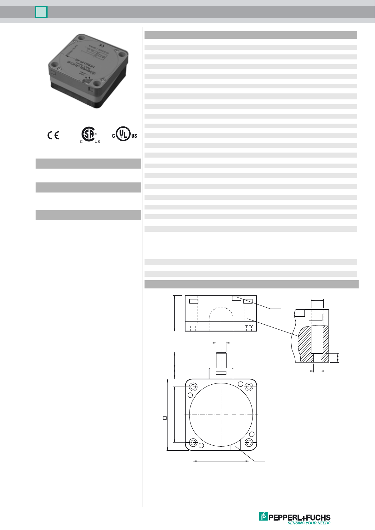
Dimensions
40
11 16
80
65
ø 9.5
LEDs
M12 x 1
7
ø 5.3
65
LEDs
Release date: 2017-02-06 11:55 Date of issue: 2017-02-06 181790_eng.xml
Refer to “General Notes Relating to Pepperl+Fuchs Product Information”.
1
Inductive sensor NCB40-FP-A2-T-P1-V1
Electrical Connection
Pinout
1
4
2
3
Wire colors in accordance with EN 60947-5-2
1 BN
2 WH
3 BU
4 BK
2
L+
L-
1
4
3
(brown)
(white)
(blue)
(black)
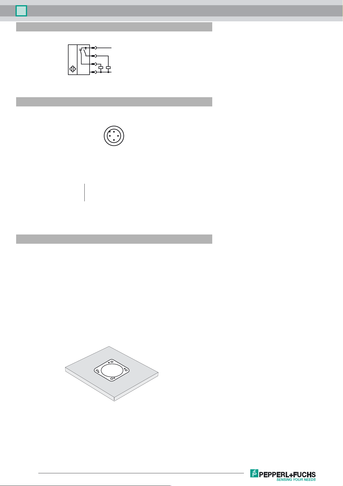
Installation Hint
These sensors are especially designed
for embeddable mounting in conveyor
floors. Due to its precise location in metal
base plates the sensor is afforded a high
degree of mechanical protection. No
clearance is required between the sensor
and the base plate, avoiding the need for
protective guarding to prevent possible
foot injury.
The large sensing range ensures positive
detection, and thus provides consistent
control and monitoring of the conveyor.
Release date: 2017-02-06 11:55 Date of issue: 2017-02-06 181790_eng.xml
Refer to “General Notes Relating to Pepperl+Fuchs Product Information”.
2
 Loading...