

Inductive sensor NCB1,5-12GM85-E2-D-V1
Technical Data
General specifications
Switching element function PNP NO
Model Number
NCB1,5-12GM85-E2-D-V1
Features
•1.5 mm flush
• Operating pressure 500 bar, peak pressure 1000 bar
• For applications in hydraulic cylinder
Accessories
V1-G
Female connector, M12, 4-pin, field attachable
V1-W
Female connector, M12, 4-pin, field attachable
V1-G-2M-PUR
Female cordset, M12, 4-pin, PUR cable
V1-W-2M-PUR
Female cordset, M12, 4-pin, PUR cable
Rated operating distance s
Installation flush
Output polarity DC
Nominal ratings
Operating voltage UB10 ... 30 V DC
Switching frequency f 0 ... 600 Hz
Hysteresis H typ. 8 %
Reverse polarity protection reverse polarity protected
Short-circuit protection pulsing
Vol tag e d rop Ud≤ 2 V
Operating current I
No-load supply current I
Limit data
Operating pressure 500 bar (7252 psi)
Peak pressure 1000 bar (14504 psi)
Functional safety related parameters
MTTFd 728 a
Mission Time (TM) 20 a
Diagnostic Coverage (DC) 0 %
Ambient conditions
Ambient temperature -25 ... 100 °C (-13 ... 212 °F)
Mechanical specifications
Connection type Connector M12 x 1 , 4-pin
Housing material Stainless steel 1.4305 / AISI 303
Sensing face Ceramic
Degree of protection IP68
Mass 42 g
Compliance with standards and directives
Stan dard conf ormit y
Sta ndar ds
Approvals and certificates
UL approval cULus Listed, General Purpose
CSA approval cCSAus Listed, General Purpose
CCC approval CCC approval / marking not required for products rated ≤36 V
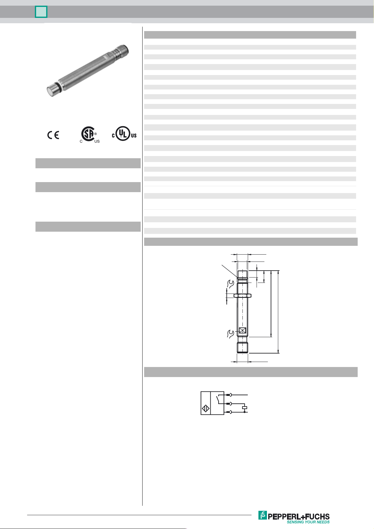
Dimensions
o-ring
5.3 x 2.4
1.5 mm
n
0 ... 200 mA
L
≤ 10 mA
0
EN 60947-5-2:2007
IEC 60947-5-2:2007
17
4
M12 x 1
ø 10e7
12.9
7.4
75
93
Release date: 2016-03-09 10:15 Date of issue: 2016-03-09 123395_eng.xml
Refer to “General Notes Relating to Pepperl+Fuchs Product Information”.
Electrical Connection
10
M12 x 1
1
4
3
L+
L-
1
Inductive sensor NCB1,5-12GM85-E2-D-V1
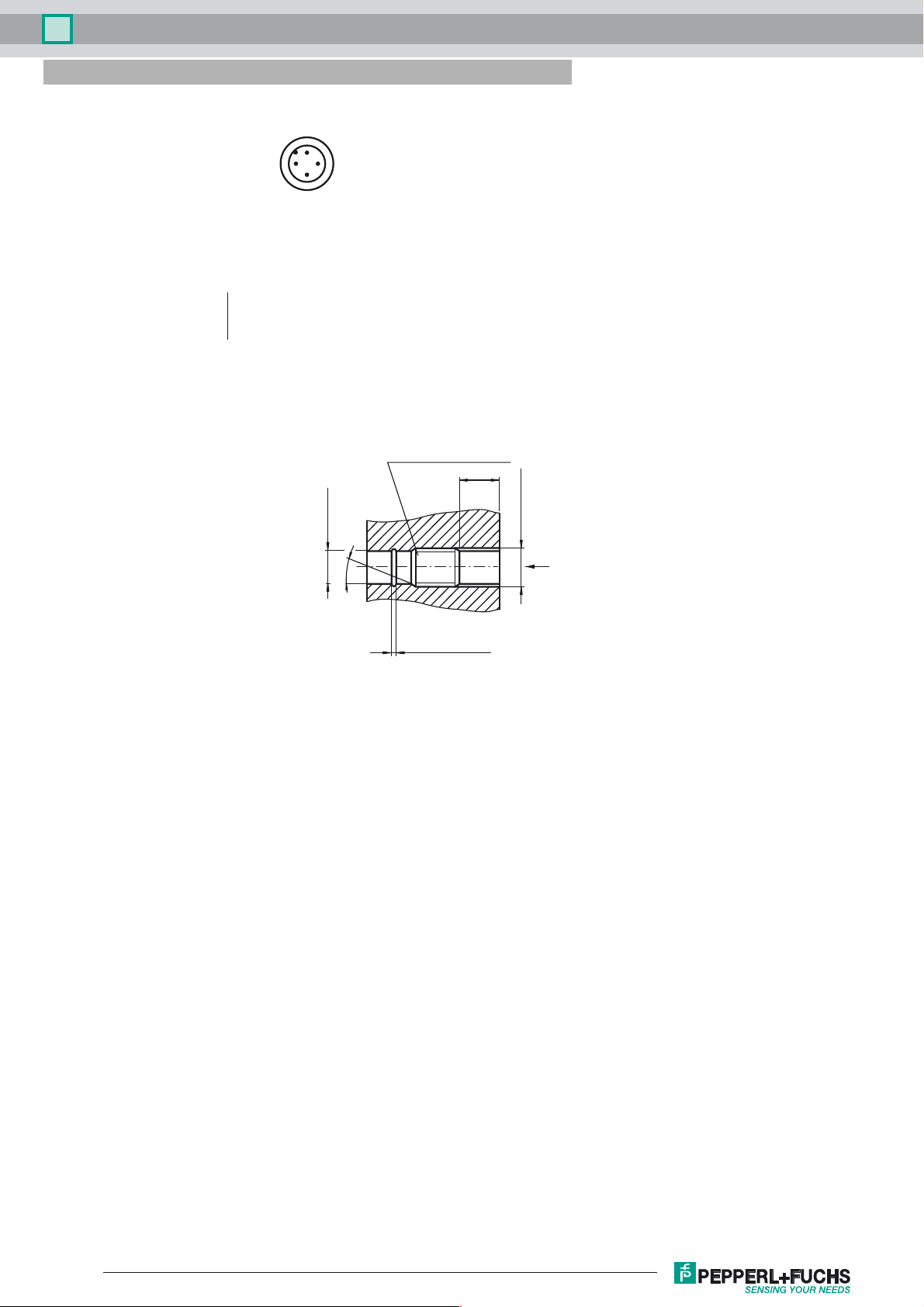
Pinout
1
2
Wire colors in accordance with EN 60947-5-2
1 BN
2 WH
3 BU
4 BK
(brown)
(white)
(blue)
(black)
4
3
Thread undercut D DIN 76
ø10 H8 (d1)
15° - 30°
L
M12 x 1 6H (d2)
installation direction
0.6 x O-cord
thickness (= 1.5)
L: recommended installation depth: L ≥ 0.8 x d2
Release date: 2016-03-09 10:15 Date of issue: 2016-03-09 123395_eng.xml
Refer to “General Notes Relating to Pepperl+Fuchs Product Information”.
2
 Loading...