

Inductive sensor NBN4-F25-E8-V1
Technical Data
General specifications
Switching function 2 x normally open (NO)
Output type PNP
Rated operating distance sn4 mm
Installation flush mountable
Output polarity DC
Model Number
NBN4-F25-E8-V1
Features
• Direct mounting on standard actuators
• Small construction with sturdy plastic
housing of protection class IP 67
•LED for power on
• M12 male connector
Accessories
BT32
Activator for F25 series
BT33
Activator for F25 series
BT34
Activator for F25 series
BT32XAS
Activator for F25 series
BT43-RG-01
Activator for F25 series including protective housing and
mounting plate
Assured operating distance s
Actual operating distance sr3.6 ... 4.4 mm typ.
Reduction factor r
Reduction factor rCu 0.4
Reduction factor r
Reduction factor r
Output type 3-wire
Nominal ratings
Operating voltage UB10 ... 30 V DC
Switching frequency f 0 ... 1000 Hz
Hysteresis H typ. 5 %
Reverse polarity protection reverse polarity protected
Short-circuit protection pulsing
Voltage drop Ud≤ 2.5 V
Design data
Operating current I
Off-state current I
No-load supply current I
Time delay before availability t
Operating voltage indicator LED, green
Switching state indicator LED, yellow
Functional safety related parameters
MTTFd 860 a
Mission Time (TM) 20 a
Diagnostic Coverage (DC) 0 %
Ambient conditions
Ambient temperature -25 ... 70 °C (-13 ... 158 °F)
Storage temperature -40 ... 85 °C (-40 ... 185 °F)
Mechanical specifications
Connection type Connector plug M12 x 1 , 4-pin
Connector housing metal
Housing material PBT
Sensing face PC
Degree of protection IP67
Mass 48 g
Tightening torque, fastening screws M5 x 25 : 2.7 Nm
Note Mounted on mechanical drive
Compliance with standards and
directives
Standard conformity
Standards
Approvals and certificates
UL approval cULus Listed
CCC approval CCC approval / marking not required for products rated ≤36 V
0.5
Al
1
304
1.1
St37
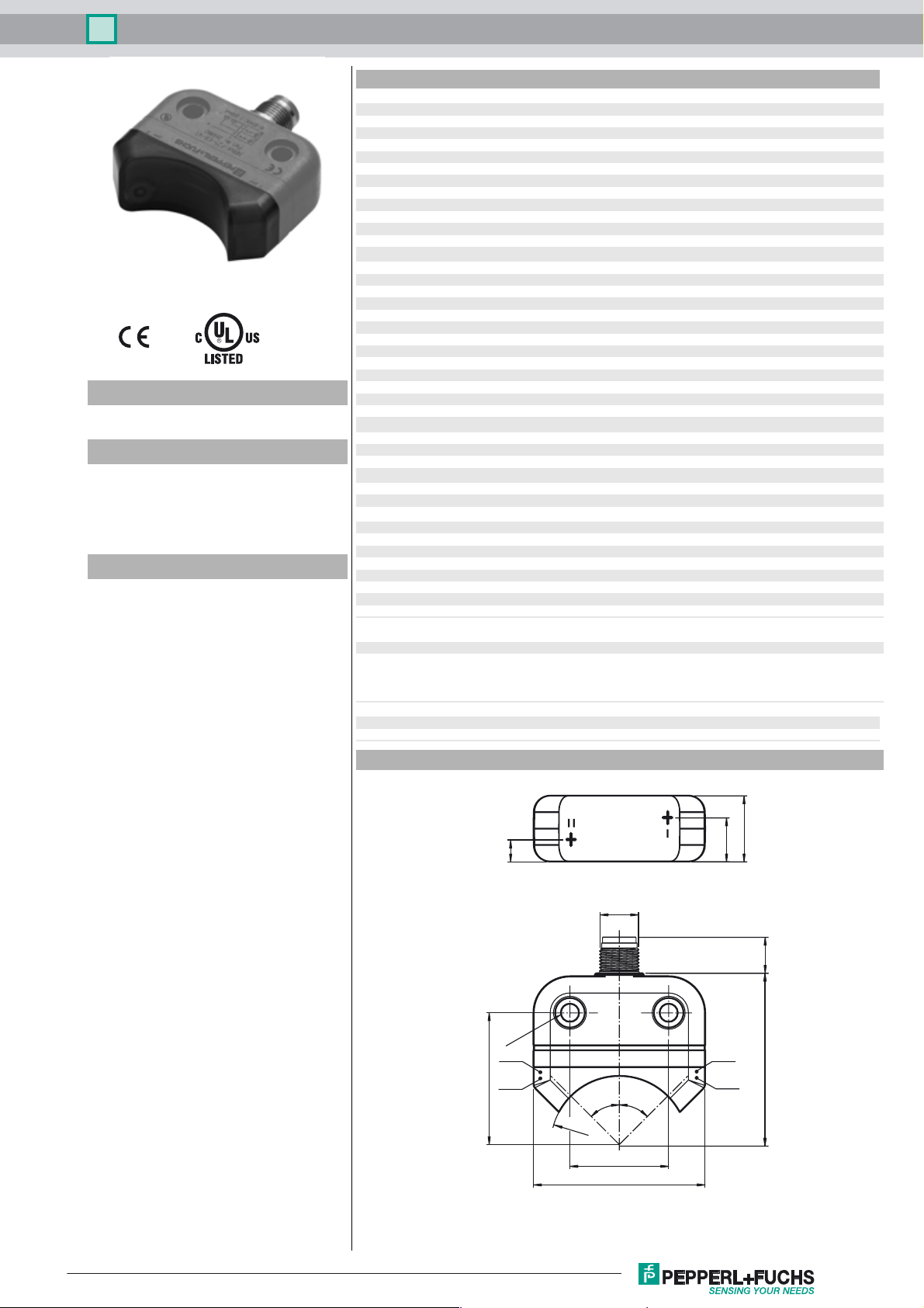
Dimensions
0 ... 3.24 mm
a
0 ... 200 mA
L
0 ... 0.5 mA typ. 0.1 µA at 25 °C
r
≤ 22.5 mA
0
≤ 100 ms
v
EN 60947-5-2:2007
EN 60947-5-2/A1:2012
IEC 60947-5-2:2007
IEC 60947-5-2 AMD 1:2012
Release date: 2017-11-22 16:26 Date of issue: 2017-11-22 264860_eng.xml
Refer to “General Notes Relating to Pepperl+Fuchs Product Information”.
20
7
13
M12x1
11
ø 5.3
LED
gn
40
LED
ye
45°45°
LED
gn
LED
ye
52
R20.8
30
52
1
Inductive sensor NBN4-F25-E8-V1
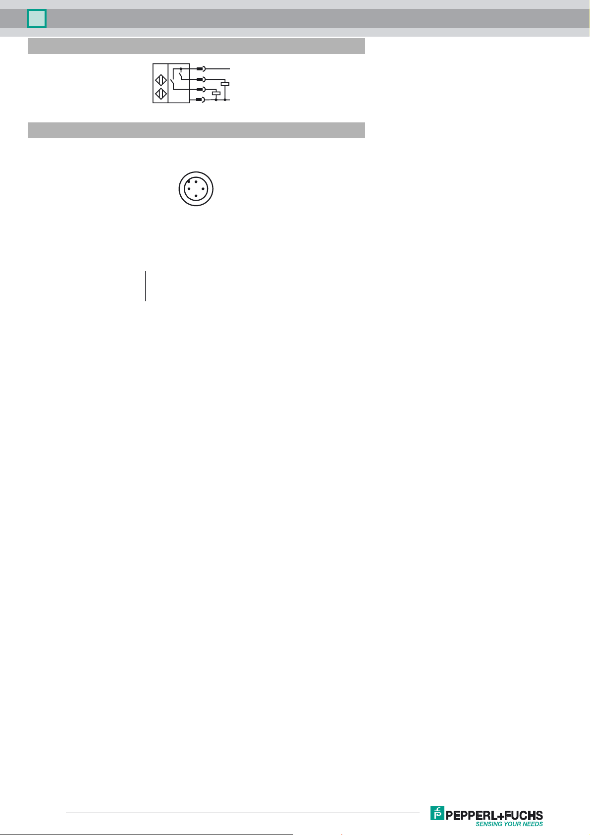
Electrical Connection
Pinout
2
II
I
1
3
(brown)
(white)
(blue)
(black)
1
4
2
3
I
I
II
Wire colors in accordance with EN 60947-5-2
1 BN
2 WH
3 BU
4 BK
L+
L-
4
Release date: 2017-11-22 16:26 Date of issue: 2017-11-22 264860_eng.xml
Refer to “General Notes Relating to Pepperl+Fuchs Product Information”.
2
 Loading...