

Pepperl Fuchs NBN40-U4K-N0 Data Sheet
Inductive sensor NBN40-U4K-N0
Technical Data
General specifications
Switching function Normally closed (NC)
Output type NAMUR
Rated operating distance sn40 mm
Installation non-flush
Assured operating distance sa0 ... 32.4 mm
Model Number
NBN40-U4K-N0
Features
• Sensor head bidirectional and
rotatable
• 40 mm non-flush
Accessories
MHW 01
Modular mounting bracket
MH 04-2057B
Mounting aid for VariKont and +U1+
Actual operating distance s
Reduction factor rAl 0.31
Reduction factor r
Reduction factor r
Output type 2-wire
Nominal ratings
Nominal voltage Uo8.2 V (Ri approx. 1 kΩ)
Switching frequency f 0 ... 150 Hz
Hysteresis H typ. 5 %
Reverse polarity protection reverse polarity protected
Short-circuit protection yes
Current consumption
Measuring plate not detected
Measuring plate detected
Switching state indicator LED, yellow
Functional safety related parameters
MTTFd 1415 a
Mission Time (TM) 20 a
Diagnostic Coverage (DC) 0 %
Ambient conditions
Ambient temperature -25 ... 100 °C (-13 ... 212 °F)
Storage temperature -40 ... 100 °C (-40 ... 212 °F)
Mechanical specifications
Connection type screw terminals
Information for connection A maximum of two conductors with the same core cross section
Core cross-section up to 2.5 mm
Minimum core cross-section
Maximum core cross-section
Housing material PA/metal
Sensing face PA
Degree of protection IP68 / IP69K
Mass 225 g
Note Tightening torque: 1.8 Nm (housing)
General information
Use in the hazardous area see instruction manuals
Category
Compliance with standards and
directives
Standard conformity
NAMUR
Electromagnetic compatibility
Standards
Approvals and certificates
UL approval cULus Listed, General Purpose
CSA approval cCSAus Listed, General Purpose
CCC approval CCC approval / marking not required for products rated ≤36 V
0.3
Cu
0.74
304
36 ... 44 mm
r
≥ 2.2 mA
≤ 1 mA
may be mounted on one terminal connection!
tightening torque 1.2 Nm + 10 %
without wire end ferrule 0.5 mm
without wire end ferrule 2.5 mm2 , with connector sleeves 1.5 mm
1G; 2G; 3G
EN 60947-5-6:2000
IEC 60947-5-6:1999
NE 21:2007
EN 60947-5-2:2007
EN 60947-5-2/A1:2012
IEC 60947-5-2:2007
IEC 60947-5-2 AMD 1:2012
2
2
, with connector sleeves 0.34 mm
2
2
Release date: 2017-11-15 13:01 Date of issue: 2017-11-15 213838_eng.xml
Refer to “General Notes Relating to Pepperl+Fuchs Product Information”.
1
Inductive sensor NBN40-U4K-N0
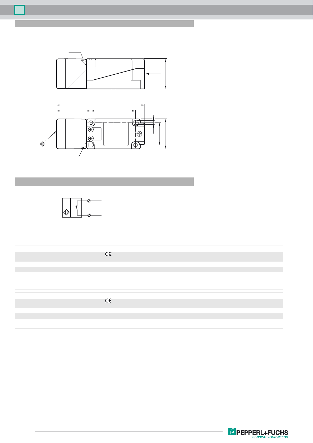
Dimensions
LED ye
LED ye
Electrical Connection
½ NPT”
40
118
6046
5.3
30
40
1
2
L+
L-
Equipment protection level Ga
CE marking 0102
Effective internal inductivity C
Effective internal inductance L
Ambient temperature Details of the correlation between the type of circuit connected, the maximum permissible ambient temperature, the
Equipment protection level Gb
CE marking 0102
Effective internal inductivity C
Effective internal inductance L
Maximum permissible ambient temperature T
i
i
i
i
≤ 105 nF ; a cable length of 10 m is considered.
≤ 300 µH ; a cable length of 10 m is considered.
temperature class, and the effective internal reactance values can be found on the EC-type examination certificate.
Use the temperature table for category 1 !!! The 20 % reduction in accordance with EN 1127-1 has already
Note:
been applied to the temperature table for category 1.
≤ 105 nF ; a cable length of 10 m is considered.
≤ 300 µH ; a cable length of 10 m is considered.
Details of the correlation between the type of circuit connected, the maximum permissible ambient temperature, the
amb
temperature class, and the effective internal reactance values can be found on the EC-type examination certificate.
Release date: 2017-11-15 13:01 Date of issue: 2017-11-15 213838_eng.xml
Refer to “General Notes Relating to Pepperl+Fuchs Product Information”.
2
 Loading...