

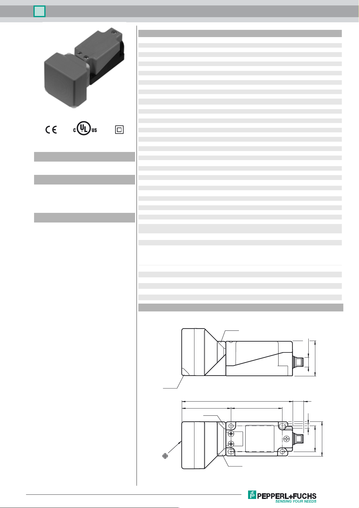
Inductive sensor NBN40-U1L-A2-V1
Technical Data
General specifications
Switching function complementary
Output type PNP
Rated operating distance sn40 mm
Installation non-flush
Output polarity DC
Model Number
NBN40-U1L-A2-V1
Features
• Sensor head bidirectional and rotatable
• 40 mm non-flush
• 4 LEDs indicator for 360° visibility
Accessories
MHW 01
Modular mounting bracket
Assured operating distance s
Actual operating distance sr36 ... 44 mm
Reduction factor r
Reduction factor rCu 0.37
Reduction factor r
Reduction factor r
Output type 4-wire
Nominal ratings
Operating voltage UB10 ... 30 V DC
Switching frequency f 0 ... 100 Hz
Hysteresis H typ. 5 %
Reverse polarity protection reverse polarity protected
Short-circuit protection pulsing
Vol tag e d rop Ud≤ 2 V
Operating current I
Off-state current I
No-load supply current I
Time delay before availability t
Operating voltage indicator LED, green
Switching state indicator LED, yellow
Functional safety related parameters
MTTFd 1310 a
Mission Time (T
Diagnostic Coverage (DC) 0 %
Ambient conditions
Ambient temperature -25 ... 85 °C (-13 ... 185 °F)
Mechanical specifications
Connection type Connector M12 x 1 , 4-pin
Housing material PA/metal
Sensing face PA
Housing base plastic
Degree of protection IP68 / IP69K
Mass 225 g
Note Tightening torque: 1.8 Nm (housing)
Compliance with standards and directives
Stan dard conf ormit y
Sta ndar ds
Approvals and certificates
Protection class II
Rated insulation voltage U
Rated impulse withstand voltage U
UL approval cULus Listed, General Purpose
CCC approval CCC approval / marking not required for products rated ≤36 V
0.39
Al
0.75
304
0.45
Brass
) 20 a
M
0 ... 32.4 mm
a
0 ... 200 mA
L
0 ... 0.5 mA typ. 0.01 mA
r
≤ 20 mA
0
120 ms
v
Tightening torque: 1.0 Nm (Screw terminal)
EN 60947-5-2:2007
EN 60947-5-2/A1:2012
IEC 60947-5-2:2007
IEC 60947-5-2 AMD 1:2012
230 V
i
2.5 kV
imp
Dimensions
LED gn
LED gn
LED ye
128 14
6057
LED ye
M12 x 1
40
5.3
30
40
Release date: 2017-03-15 17:13 Date of issue: 2017-03-15 214023_eng.xml
Refer to “General Notes Relating to Pepperl+Fuchs Product Information”.
1
Inductive sensor NBN40-U1L-A2-V1
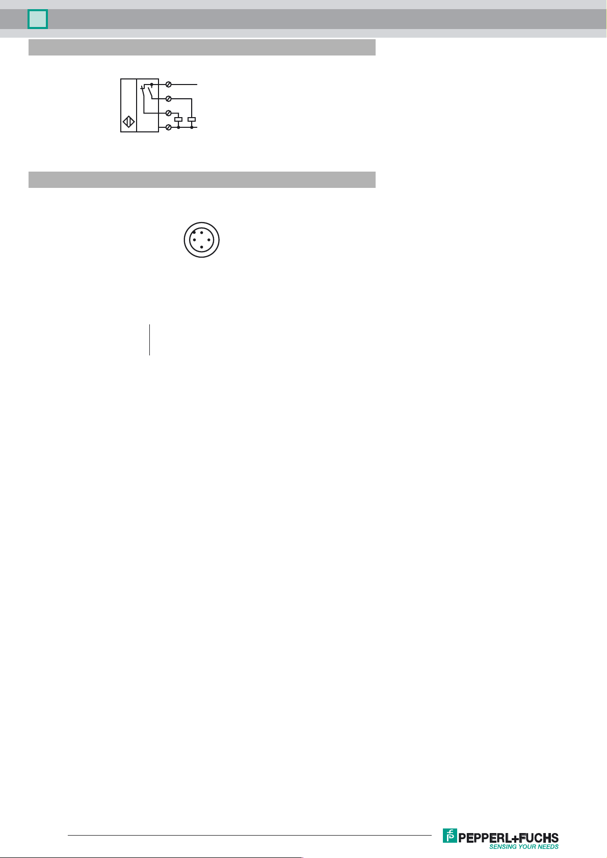
Electrical Connection
Pinout
1
4
2
3
Wire colors in accordance with EN 60947-5-2
1 BN
2 WH
3 BU
4 BK
2
L+
L-
1
4
3
(brown)
(white)
(blue)
(black)
Release date: 2017-03-15 17:13 Date of issue: 2017-03-15 214023_eng.xml
Refer to “General Notes Relating to Pepperl+Fuchs Product Information”.
2
 Loading...