

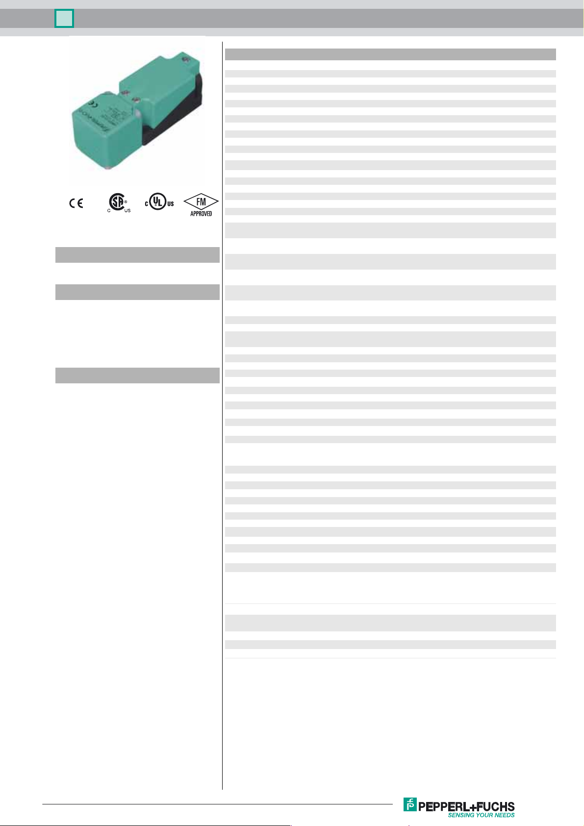
Inductive sensor NBN40-U1K-E2-3G-3D
Technical Data
General specifications
Switching function Normally open (NO)
Output type PNP
Rated operating distance sn40 mm
Installation non-flush
Output polarity DC
Model Number
NBN40-U1K-E2-3G-3D
Features
• Sensor head bidirectional and rotatable
• 40 mm non-flush
•3-wire DC
• 4 LEDs indicator for 360° visibility
• ATEX-approval for zone 2 and zone 22
Accessories
MHW 01
Modular mounting bracket
Assured operating distance s
Actual operating distance sr36 ... 44 mm typ. 40 mm
Reduction factor r
Reduction factor rCu 0.3
Reduction factor r
Reduction factor r
Output type 3-wire
Nominal ratings
Operating voltage UB10 ... 30 V DC
Switching frequency f 0 ... 150 Hz
Hysteresis H typ. 5 %
Reverse polarity protection reverse polarity protected
Short-circuit protection pulsing
Vol tag e d rop Ud≤ 2 V
Vol tag e d rop at I
Vol tage dro p IL = 1 mA, switching element
on U
d
Vol tag e dr op I
on U
d
Vol tag e dr op IL = 20 mA, switching element
on U
d
Vol tag e dr op I
on U
d
Vol tage dro p IL = 100 mA, switching element on U
Vol tage dro p I
ment on U
Operating current I
Off-state current I
Off-state current TU =40 °C, switching ele-
ment off
No-load supply current I
Time delay before availability t
Operating voltage indicator LED, green
Switching state indicator LED, yellow
Functional safety related parameters
MTTFd 1358 a
Mission Time (T
Diagnostic Coverage (DC) 0 %
Ambient conditions
Ambient temperature -25 ... 85 °C (-13 ... 185 °F)
Mechanical specifications
Connection type screw terminals
Information for connection A maximum of two conductors with the same core cross section
Core cross-section up to 2.5 mm
Minimum core cross-section
Maximum core cross-section
Housing material PA
Sensing face PA
Degree of protection IP68 / IP69K
Mass 225 g
Note Tightening torque: 1.8 Nm (housing)
General information
Use in the hazardous area see instruction manuals
Category
Compliance with standards and directives
Stan dard conf ormit y
Sta ndar ds
Approvals and certificates
FM approval hazardous (classified) location
UL approval cULus Listed, General Purpose
CSA approval cCSAus Listed, General Purpose
CCC approval CCC approval / marking not required for products rated ≤36 V
0.31
Al
0.74
304
0.39
Brass
L
= 10 mA, switching element
L
= 50 mA, switching element
L
d
= 200 mA, switching ele-
L
d
) 20 a
M
0 ... 32.4 mm
a
0.5 ... 2.3 V typ. 0.9 V
0.8 ... 2.2 V typ. 1.4 V
0.9 ... 2.3 V typ. 1.5 V
0.9 ... 2.5 V typ. 1.6 V
1 ... 2.6 V typ. 1.8 V
1.2 ... 2.8 V typ. 2 V
0 ... 200 mA
L
0 ... 0.5 mA typ. 0.01 mA
r
≤ 100 µA
≤ 20 mA
0
80 ms
v
may be mounted on one terminal connection!
tightening torque 1.2 Nm + 10 %
without wire end ferrule 0.5 mm
without wire end ferrule 2.5 mm2 , with connector sleeves 1.5 mm
3G; 3D
EN 60947-5-2:2007
EN 60947-5-2/A1:2012
IEC 60947-5-2:2007
IEC 60947-5-2 AMD 1:2012
Non-incendive
2
2
, with connector sleeves 0.34 mm
2
2
Release date: 2017-05-17 11:37 Date of issue: 2017-05-17 209264_eng.xml
Refer to “General Notes Relating to Pepperl+Fuchs Product Information”.
1
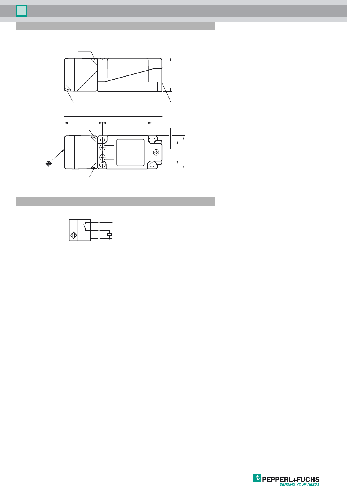
Inductive sensor NBN40-U1K-E2-3G-3D
Dimensions
LED ye
40
LED gn
Electrical Connection
LED gn
LED ye
BN
BK
BU
118
M20 x 1.5
6046
5.3
30
40
L+
L-
Release date: 2017-05-17 11:37 Date of issue: 2017-05-17 209264_eng.xml
Refer to “General Notes Relating to Pepperl+Fuchs Product Information”.
2
 Loading...