

Inductive sensor NBN40-U1-A2
Technical Data
General specifications
Switching element function PNP NO/NC
Model Number
NBN40-U1-A2
Features
• Sensor head bidirectional and rotatable
• 40 mm non-flush
•4-wire DC
• 4 LEDs indicator for 360° visibility
Accessories
V1-M20-80
Receptacles, M12/M20; plastic version
MHW 01
Modular mounting bracket
Rated operating distance s
Installation non-flush
Output polarity DC
Assured operating distance sa0 ... 32.4 mm
Reduction factor r
Reduction factor rCu 0.3
Reduction factor r
Reduction factor r
Nominal ratings
Operating voltage UB10 ... 30 V DC
Switching frequency f 0 ... 180 Hz
Hysteresis H typ. 5 %
Reverse polarity protection reverse polarity protected
Short-circuit protection pulsing
Vol tag e d rop U
Operating current I
Off-state current I
No-load supply current I
Time delay before availability t
Operating voltage indicator LED, green
Switching state indicator LED, yellow
Functional safety related parameters
MTTFd 1230 a
Mission Time (TM) 20 a
Diagnostic Coverage (DC) 0 %
Ambient conditions
Ambient temperature -25 ... 85 °C (-13 ... 185 °F)
Mechanical specifications
Connection type screw terminals
Information for connection A maximum of two conductors with the same core cross-section
Core cross-section up to 2.5 mm
Minimum core cross-section
Maximum core cross-section
Housing material PA/metal with epoxy powder coating
Sensing face PA
Housing base plastic
Degree of protection IP68 / IP69K
Mass 225 g
Note Tightening torque: 1.8 Nm (housing)
Compliance with standards and directives
Stan dard conf ormit y
Sta ndar ds
Approvals and certificates
EAC conformity TR CU 020/2011
UL approval cULus Listed, General Purpose
CCC approval CCC approval / marking not required for products rated ≤36 V
0.31
Al
0.74
304
0.39
Brass
40 mm
n
≤ 2 V
d
0 ... 200 mA
L
0 ... 0.5 mA
r
≤ 20 mA
0
80 ms
v
may be mounted on one terminal connection!
tightening torque 1.2 Nm + 10 %
without wire end ferrule 0.5 mm2 , with connector sleeves 0.34 mm
without wire end ferrule 2.5 mm
EN 60947-5-2:2007
IEC 60947-5-2:2007
2
2
, with connector sleeves 1.5 mm
2
2
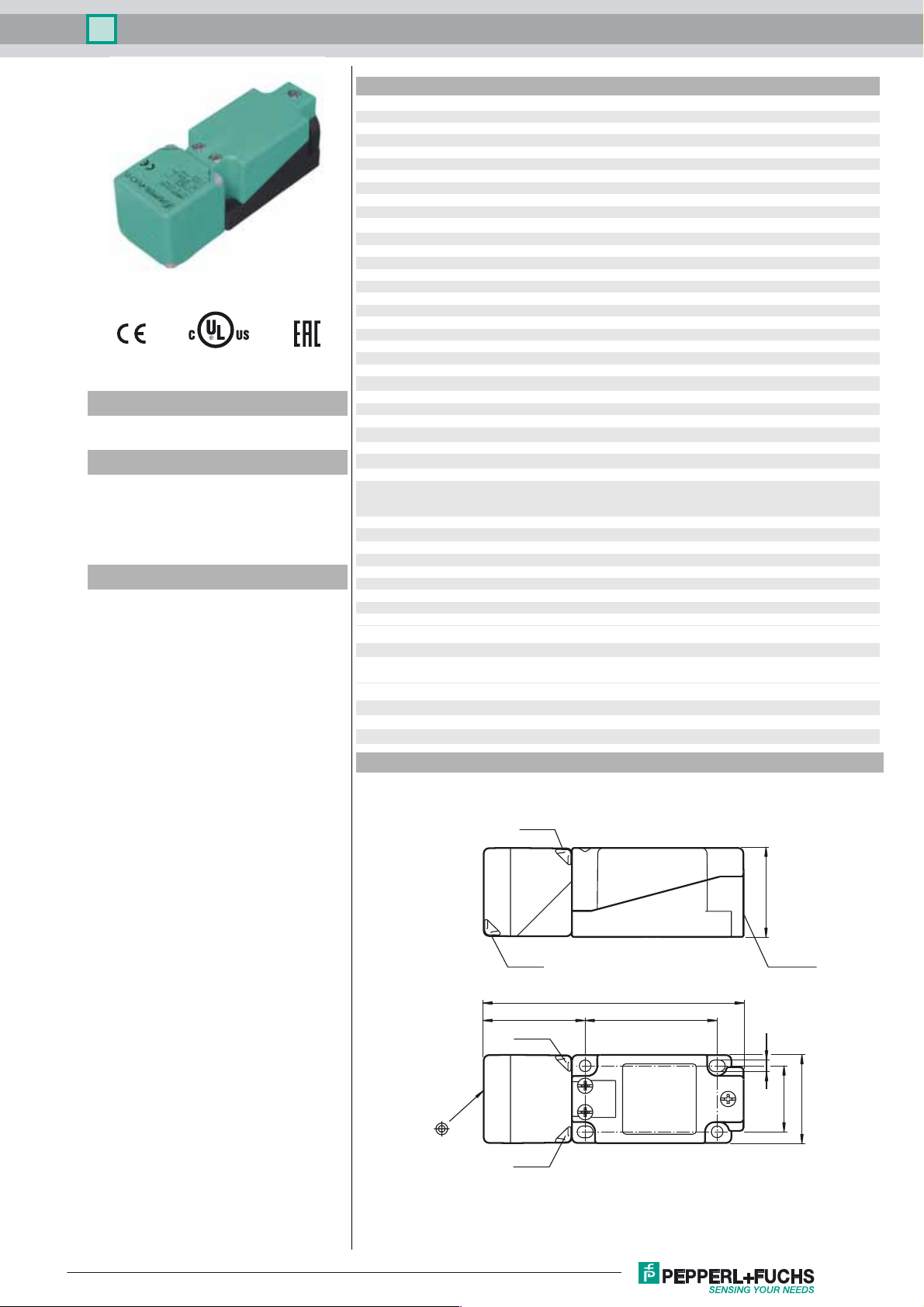
Dimensions
LED ye
LED gn
LED gn
LED ye
118
40
M20 x 1.5
6046
5.3
30
40
Release date: 2016-09-29 11:36 Date of issue: 2016-10-10 194788_eng.xml
Refer to “General Notes Relating to Pepperl+Fuchs Product Information”.
1
Inductive sensor NBN40-U1-A2
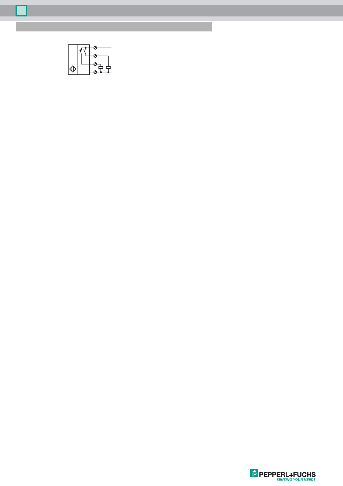
Electrical Connection
1
4
2
3
L+
L-
Release date: 2016-09-29 11:36 Date of issue: 2016-10-10 194788_eng.xml
Refer to “General Notes Relating to Pepperl+Fuchs Product Information”.
2
 Loading...