

Pepperl Fuchs NBN3-F31K-E8-V1-V1 Data Sheet
Inductive sensor NBN3-F31K-E8-V1-V1
Technical Data
General specifications
Switching function 2 x normally open (NO)
Output type PNP
Rated operating distance sn3 mm
Installation flush mountable
Output polarity DC
Model Number
NBN3-F31K-E8-V1-V1
Features
• Direct mounting on standard actuators
• Compact and stable housing
• Fixed setting
•LED for power on
• LEDs for switching state of sensor and
solenoid valve
Application
Note
The connections to this sensor are sealed
with stopping plugs to protect against dirt and
moisture. If not all of the connections are
used in your application, then seal the remaining stopping plugs on the sensor permanently or check during initial installation and
when performing regular maintenance work
that the stopping plugs are secure and impermeable. If necessary, tighten the stopping
plugs to a torque of 1 Nm.
Accessories
VMA-2+P/Z2-0,3M-PVC-V1-W-Y
Valve connector, Form A on M12, 2+PE, LED, Z diode, PVC
cable
VMC-2+P/Z2-0,3M-PVC-V1-W-Y
Valve connector, Form C on M12, 2+PE, LED, Z diode, PVC
cable
VMCI-2+P/Z2-0,3M-PVC-V1-W-Y
Valve connector, Form C (Ind) on M12, 2+PE, LED, Z diode,
PVC cable
VMB-2+P/Z2-0,3M-PVC-V1-W-Y
Valve connector, Form B on M12, 2+PE, LED, Z diode, PVC
cable
VMBI-2+P/Z2-0,3M-PVC-V1-W-Y
Valve connector, Form B (Ind) on M12, 2+PE, LED, Z diode,
PVC cable
BT65A
Activator for F31 series
BT65X
Activator for F31 series
BT115A
Activator for F31 series
BT115X
Activator for F31 series
BT65B
Activator for F31 series
BT115B
Activator for F31 series
Assured operating distance s
Actual operating distance sr2.7 ... 3.3 mm typ.
Reduction factor r
Reduction factor rCu 0.4
Reduction factor r
Reduction factor r
Output type 4-wire
Nominal ratings
Operating voltage UB10 ... 30 V DC
Switching frequency f 0 ... 500 Hz
Hysteresis H typ. 5 %
Reverse polarity protection all connections
Short-circuit protection pulsing
Voltage drop Ud≤ 3 V
Operating current I
Off-state current I
No-load supply current I
Operating voltage indicator LED, green
Switching state indicator LED, yellow
Valve status indicator LED, yellow
Functional safety related parameters
MTTFd 780 a
Mission Time (T
Diagnostic Coverage (DC) 0 %
Valve circuit
Voltage max. 32 V DC
Current max. 240 mA
Short-circuit protection no
Reverse polarity protection yes, with reversed output LED is out of function, therfore more
Ambient conditions
Ambient temperature -25 ... 70 °C (-13 ... 158 °F)
Mechanical specifications
Connection (system side) Cage tension spring terminals
Core cross-section (system side) 1.5/2.5 mm2 flexible/rigid
Connection (valve side) 4-pin, M12 x 1 socket
Housing material PBT
Sensing face PBT
Degree of protection IP67
Tightening torque, housing screws 1 Nm
Tightening torque, cable gland M20 x 1.5 ; ≤ 7 Nm
Compliance with standards and
directives
Standard conformity
Standards
Approvals and certificates
UL approval cULus Listed, General Purpose
CSA approval cCSAus Listed, General Purpose
CCC approval CCC approval / marking not required for products rated ≤36 V
0.5
Al
1
304
1.2
St37
) 20 a
M
0 ... 2.43 mm
a
0 ... 100 mA
L
0 ... 0.5 mA typ. 0.1 µA
r
≤ 25 mA
0
power for solenoid valve
EN 60947-5-2:2007
EN 60947-5-2/A1:2012
IEC 60947-5-2:2007
IEC 60947-5-2 AMD 1:2012
Release date: 2018-02-05 13:48 Date of issue: 2018-02-07 097642_eng.xml
Refer to “General Notes Relating to Pepperl+Fuchs Product Information”.
1
Inductive sensor NBN3-F31K-E8-V1-V1
V1
V2
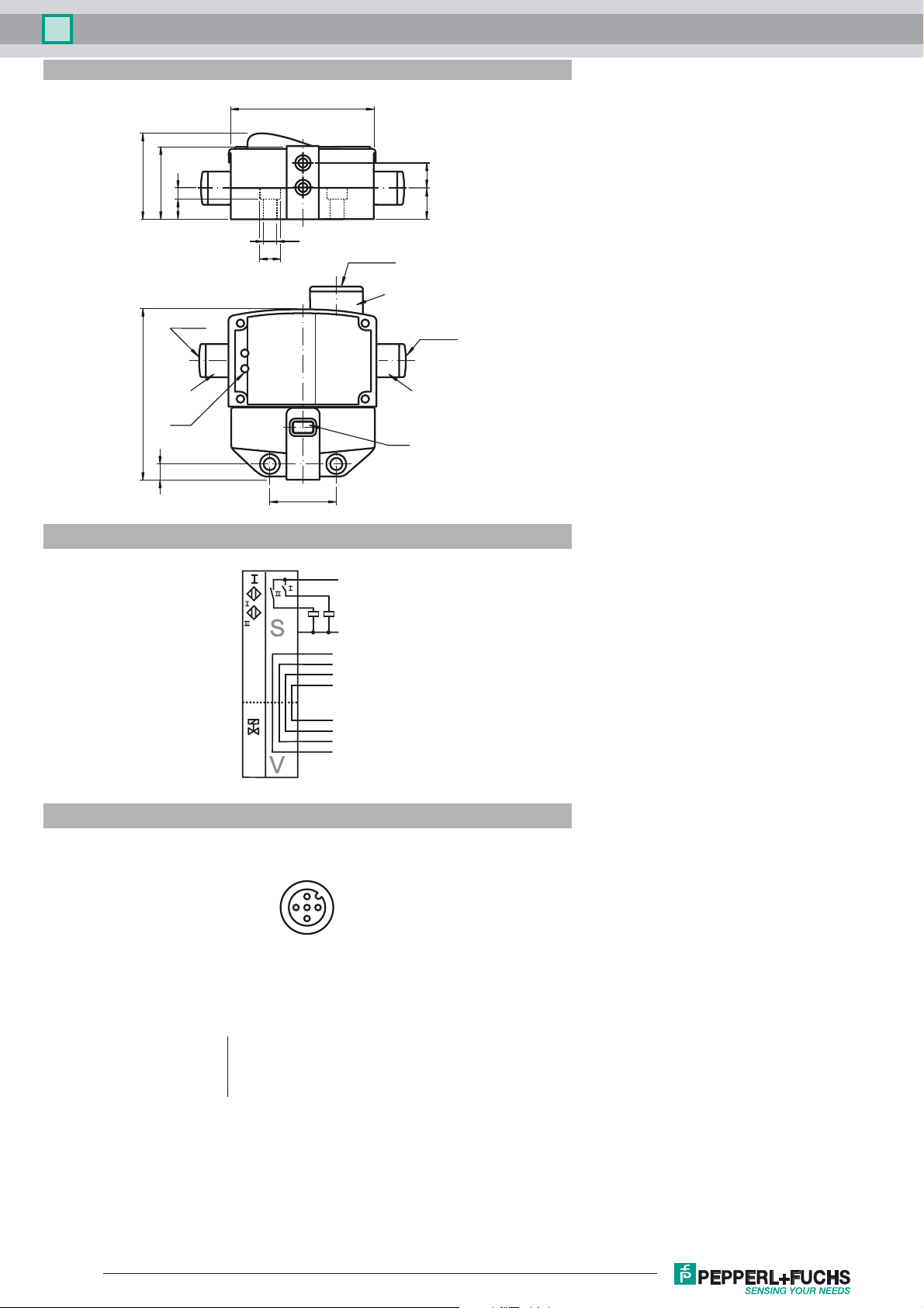
Dimensions
65
I
40
35
95
9
II
14 11
5.4
M20 x 1.5
S
M12 x 1
M12 x 1
V2
77.5
LED
7
Electrical Connection
Pinout
E8-V1-V1
30
4
5
1
2
9 (10)
10 (9)
6 (7)
7 (6)
3 (1)
1 (3)
3 (1)
1 (3)
L+
L-
V1+
V1V2+
V2-
V2V2+
V1V1+
V1
LED
1
4
Wire colors in accordance with EN 60947-5-2
1 BN
2 WH
3 BU
4 BK
5 GY
(brown)
(white)
(blue)
(black)
(gray)
Refer to “General Notes Relating to Pepperl+Fuchs Product Information”.
2
3
Release date: 2018-02-05 13:48 Date of issue: 2018-02-07 097642_eng.xml
2
 Loading...