

Pepperl Fuchs NBN3-F31K2-Z8L-B33-S Data Sheet
Inductive sensor NBN3-F31K2-Z8L-B33-S
II
Technical Data
General specifications
Switching function 2 x normally open (NO)
Output type Two-wire
Rated operating distance sn2.5 mm
Installation for non-flush mounting
Output polarity DC
Model Number
NBN3-F31K2-Z8L-B33-S
Features
• Direct mounting on standard actuators
• Compatible with all process control
systems
• 2 solenoid valves can be connected
• Weatherproof housing for outdoor
applications
• Temperature range -40 ... 167 °F (-40°C
to 75°C)
• 2-wire DC sensor with minimum offstate current
• LEDs for switching state of sensor and
solenoid valve
• Plug-in terminals
Application
Note
The connections to this sensor are sealed
with stopping plugs to protect against dirt and
moisture. If not all of the connections are
used in your application, then seal the remaining stopping plugs on the sensor permanently or check during initial installation and
when performing regular maintenance work
that the stopping plugs are secure and impermeable. If necessary, tighten the stopping
plugs to a torque of 1 Nm.
Assured operating distance s
Output type 2x 2-wire
Nominal ratings
Operating voltage UB6 ... 30 V
Switching frequency f 0 ... 100 Hz
Hysteresis H typ. 0.5 mm
Reverse polarity protection reverse polarity tolerant
Short-circuit protection no
Voltage drop U
Operating current I
Off-state current I
Switching state indicator LED, yellow
Valve status indicator LED, yellow
Functional safety related parameters
MTTFd 684 a
Mission Time (TM) 20 a
Diagnostic Coverage (DC) 0 %
Valve circuit
Voltage max. 32 V DC
Current max. 240 mA
Short-circuit protection no
Reverse polarity protection yes, with reversed output LED is out of function, therfore more
Ambient conditions
Ambient temperature -40 ... 75 °C (-40 ... 167 °F)
Storage temperature -40 ... 85 °C (-40 ... 185 °F)
Mechanical specifications
Connection (system side) screw terminal , M20 x 1.5 cable gland
Core cross-section (system side) 1.5/2.5 mm2 flexible/rigid
Connection (valve side) 4-pin, M12 x 1 socket
Housing material rugged, translucent polycarbonate (PC) optimised for outdoor use
Housing base PC
Degree of protection IP66 / IP67 / IP69
Tightening torque, housing screws ≤ 2 Nm
Tightening torque, cable gland M20 x 1.5 ; ≤ 4 Nm
Tightening torque, stopping plug 1 Nm
Tightening torque Male connector , 1 Nm
Compliance with standards and
directives
Standard conformity
Standards
Approvals and certificates
EAC conformity TR CU 020/2011
UL approval cULus Listed, General Purpose, Class 2 Power Source
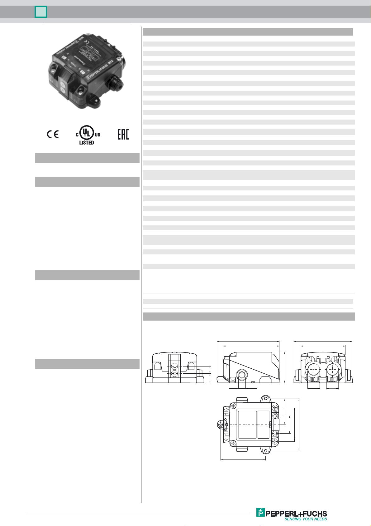
Dimensions
0 ... 2.05 mm
a
≤ 6 V
d
4 ... 100 mA
L
100 ... 200 µA typ. 160 µA
r
power for solenoid valve
M12 x 1 ≤ 3 Nm
EN 60947-5-2:2007
EN 60947-5-2/A1:2012
IEC 60947-5-2:2007
IEC 60947-5-2 AMD 1:2012
VDI / VDE 3845
106
95
100
75
Accessories
BT65-F31K2-RG-EN
Activator for F31K2 series
BT65A
Activator for F31 series
BT65X
Activator for F31 series
VMB-2+P/Z2-0,3M-PVC-V1-W-Y
Valve connector, Form B on M12, 2+PE, LED, Z diode, PVC
cable
VMBI-2+P/Z2-0,3M-PVC-V1-W-Y
Valve connector, Form B (Ind) on M12, 2+PE, LED, Z diode,
PVC cable
VMC-2+P/Z2-0,3M-PVC-V1-W-Y
Valve connector, Form C on M12, 2+PE, LED, Z diode, PVC
cable
VMCI-2+P/Z2-0,3M-PVC-V1-W-Y
Valve connector, Form C (Ind) on M12, 2+PE, LED, Z diode,
PVC cable
VMA-2+P/Z2-0,3M-PVC-V1-W-Y
Valve connector, Form A on M12, 2+PE, LED, Z diode, PVC
cable
Release date: 2018-03-08 13:12 Date of issue: 2018-03-08 260495_eng.xml
Refer to “General Notes Relating to Pepperl+Fuchs Product Information”.
I
II
1114
M12x1
78
53
44.5
M20x1,5 M20x1,5
57
30
89
1
Inductive sensor NBN3-F31K2-Z8L-B33-S
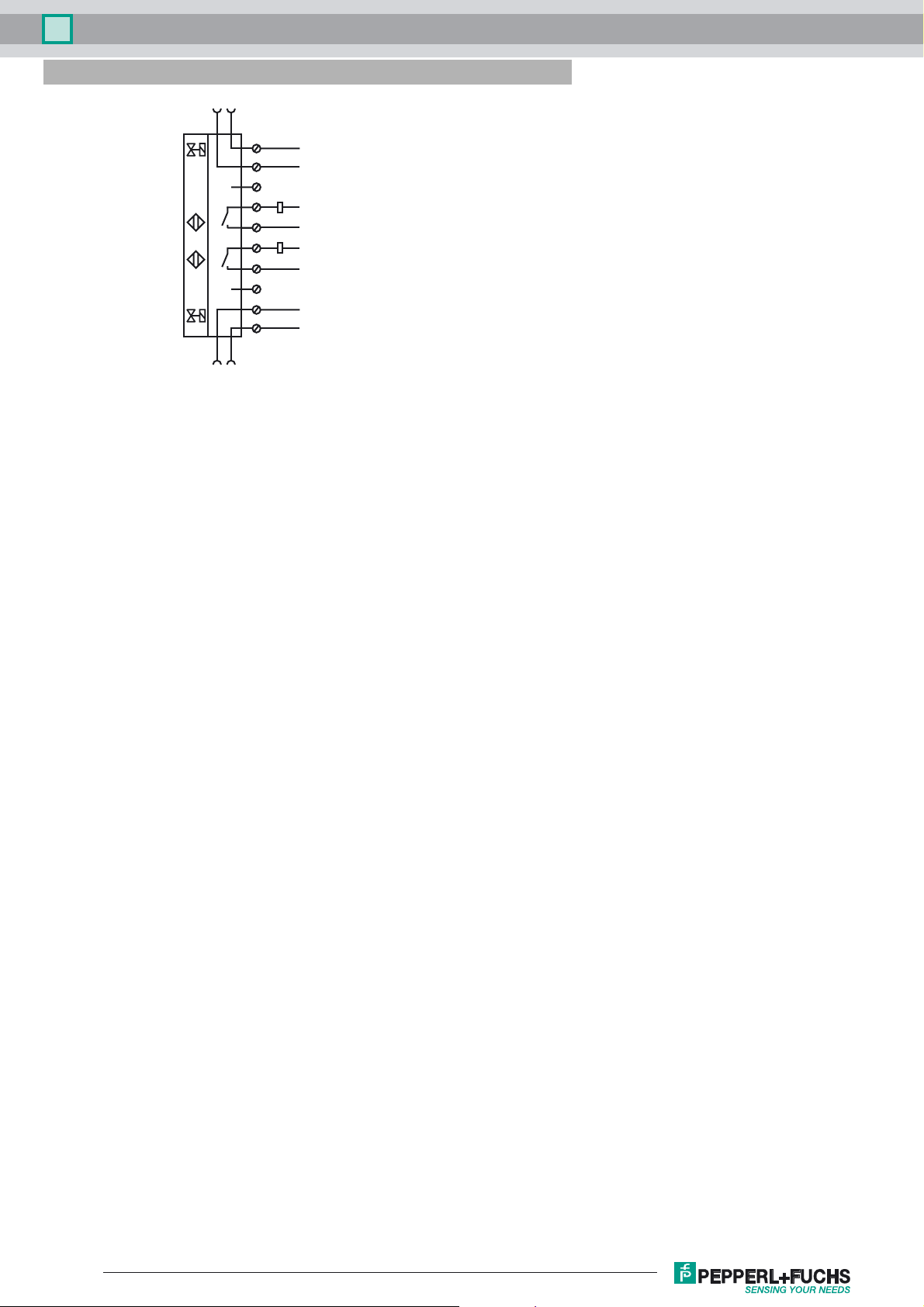
Electrical Connection
VII+
VII-
3
1=4
10
VI-
9
8
7
6
5
4
3
2
1
3
1=4
VI+
II
II
I
I
VII+
VII-
S
S
S
S
VI-
VI+
II-
II+
I-
I+
Release date: 2018-03-08 13:12 Date of issue: 2018-03-08 260495_eng.xml
Refer to “General Notes Relating to Pepperl+Fuchs Product Information”.
2
 Loading...