

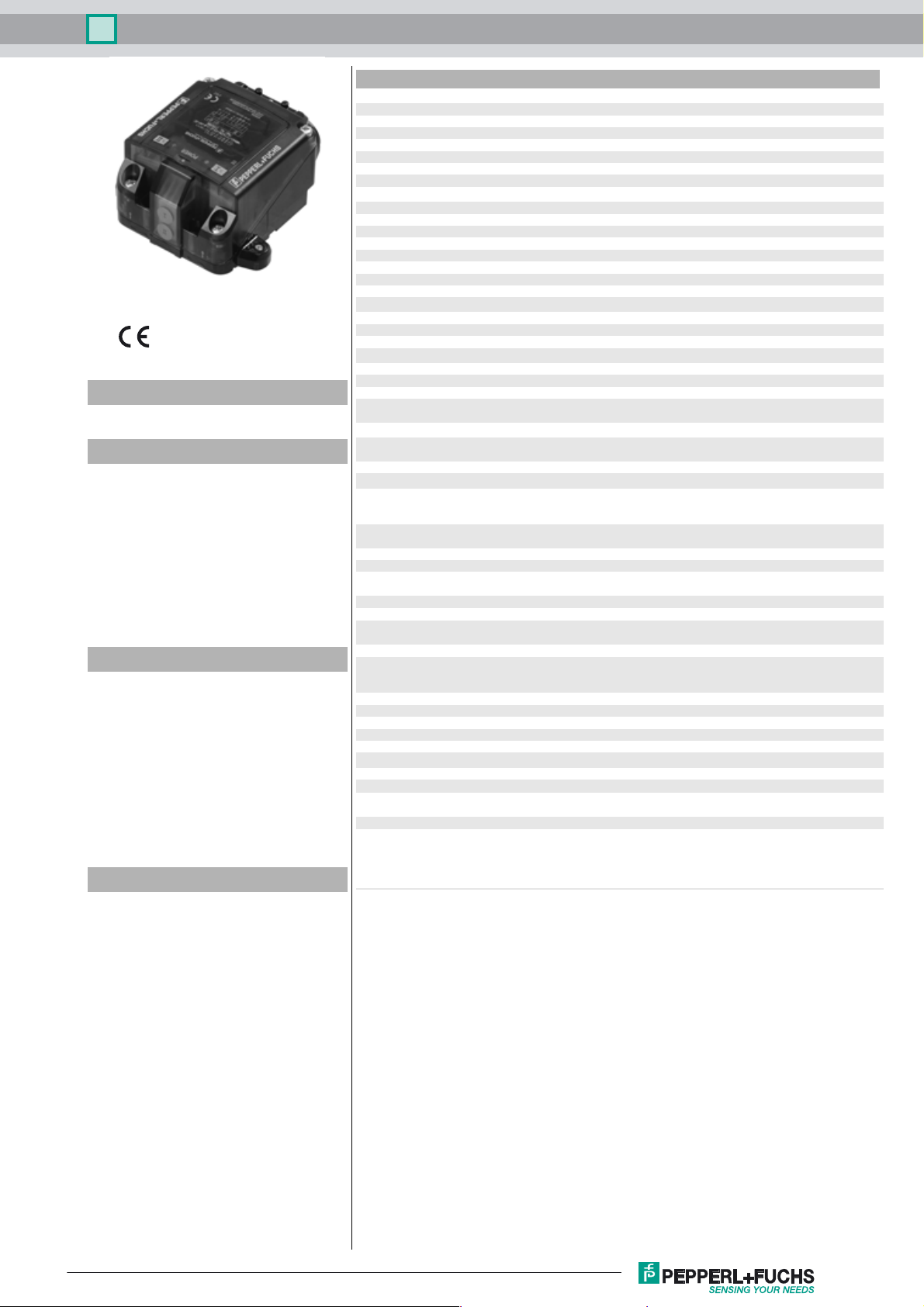
Inductive sensor NBN3-F31K2M-Z8L-B13-S-3G-3D
Technical Data
General specifications
Switching function 2 x normally open (NO)
Output type Two-wire
Rated operating distance sn2.5 mm
Installation for non-flush mounting
Output polarity DC
Model Number
NBN3-F31K2M-Z8L-B13-S-3G-3D
Features
• Direct mounting on standard actuators
• Compact and stable housing
• ATEX-approval for zone 2 and zone 22
• Compatible with all process control
systems
• 2-wire DC sensor with minimum offstate current
•Rugged metal base
• Weatherproof housing for outdoor
applications
• Plug-in terminals
Application
Note
The connections to this sensor are sealed
with stopping plugs to protect against dirt and
moisture. If not all of the connections are
used in your application, then seal the remaining stopping plugs on the sensor permanently or check during initial installation and
when performing regular maintenance work
that the stopping plugs are secure and impermeable. If necessary, tighten the stopping
plugs to a torque of 2 Nm.
Accessories
BT65-F31K2-RG-EN-01
Activator for F31K2 series including protective housing
SH-F31K2-B13
Protective cap for mechanically protected mounting
SH-BT65-F31K2-01
Protective housing for activator BT65-F31K2-RG-EN-01
Assured operating distance s
Output type 2x 2-wire
Nominal ratings
Operating voltage UB6 ... 30 V
Switching frequency f 0 ... 100 Hz
Hysteresis H typ. 0.5 mm
Reverse polarity protection reverse polarity tolerant
Short-circuit protection no
Voltage drop U
Operating current I
Off-state current I
Functional safety related parameters
MTTFd 684 a
Mission Time (TM) 20 a
Diagnostic Coverage (DC) 0 %
Valve circuit
Voltage max. 32 V DC
Current max. 240 mA
Short-circuit protection no
Reverse polarity protection yes, with reversed output LED is out of function, therfore more
Ambient conditions
Ambient temperature -40 ... 75 °C (-40 ... 167 °F) , restriction for use in hazardous area,
Storage temperature -40 ... 85 °C (-40 ... 185 °F)
Mechanical specifications
Connection (system side) M20 x 1.5 cable gland , ground connection with earthing screw only
Connection (valve side) screw terminal ,
Housing material rugged polycarbonate (PC) + GF 10% , optimised for outdoor use
Housing base powder coated aluminum
Degree of protection IP67 ; additional degree of protection IP66/IP69 with BT65-F31K2-
Terminal assembly
Number
Connection type
Type
Terminal capacity
Tightening torque, fastening screws 2 Nm
Tightening torque, housing screws 1.5 Nm
Tightening torque, earthing screw 1.5 Nm
Tightening torque, cable gland ≤ 4 Nm
Tightening torque, stopping plug 2 Nm
General information
Use in the hazardous area see instruction manuals
Category
Compliance with standards and
directives
Standard conformity
Standards
0 ... 2.05 mm
a
≤ 6 V
d
4 ... 100 mA
L
100 ... 200 µA typ. 160 µA
r
power for solenoid valve
see instruction manual
for wire cross-section 4 mm
wire end ferrule
Cable gland M20 x 1.5
RG-EN-01 and SH-F31K2-B13
10
For connection of copper wires with 7 mm dismantle length
Tightening torque 0.5 ... 0.6 Nm
Screw terminal block, pluggable
Conductor cross-section 0,25 ... 2,5 mm2 , flexible/rigid
For Multiple-wire connection: two wires of equal cross-section per
0.25 ... 1 mm
3G; 3D
EN 60947-5-2:2007
EN 60947-5-2/A1:2012
IEC 60947-5-2:2007
IEC 60947-5-2 AMD 1:2012
VDI / VDE 3845
2
2
, use solid wire or stranded wire with
Release date: 2018-03-08 13:11 Date of issue: 2018-03-08 235084_eng.xml
Refer to “General Notes Relating to Pepperl+Fuchs Product Information”.
1
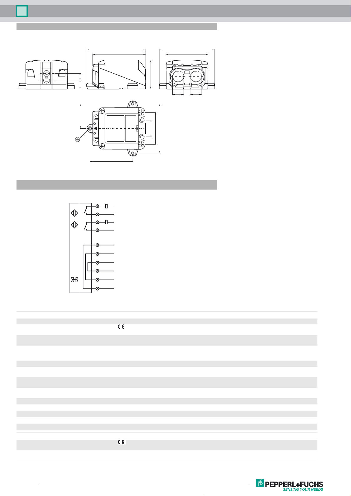
Inductive sensor NBN3-F31K2M-Z8L-B13-S-3G-3D
II
Dimensions
I
II
Electrical Connection
II
I
106
95
1114
44.5
78
7
6
5
4
S
II-
S
II+
S
I-
S
I+
53
57
30
89
100
75
B13
M20 M20
10
9
V+
V-
8
3
2
1
Shield
V-
V+
Equipment protection level Gc (nA)
Certificate PF 15CERT3754 X
CE marking
ATEX marking ¬ II 3G Ex nA IIC T6...T1 Gc
Standards EN 60079-0:2012+A11:2013, EN 60079-15:2010
The Ex-related marking can also be printed on the enclosed label.
Ignition protection category "n"
Use is restricted to the following stated conditions
Special conditions
Maximum operating current I
Maximum operating voltage U
L
Bmax
Maximum permissible ambient temperature T
at U
at U
at U
at U
=30 V, IL=100 mA, T6
Bmax
=30 V, IL=100 mA, T1 ... T5
Bmax
=30 V, IL=50 mA, T6
Bmax
=30 V, IL=50 mA, T1 ... T5
Bmax
Maximum values of the valve circuit
The maximum permissible load current must be restricted to the values given in the following list. High load currents
and load short-circuits are not permitted.
The maximum permissible operating voltage UB max is restricted to the values in the following list. Tolerances are
not permissible.
Depending on the load current I
Umax
Details can be found in the following list.
, the maximum operating voltage U
L
35 °C (95 °F)
57 °C (134.6 °F)
35 °C (95 °F)
60 °C (140 °F)
UV = 32 V; IV = 240 mA
Equipment protection level Dc (tc)
CE marking
, and the temperature class.
Bmax
ATEX marking ¬ II 3D Ex tc IIIC T80°C Dc
Refer to “General Notes Relating to Pepperl+Fuchs Product Information”.
The Ex-related marking can also be printed on the enclosed label.
2
Release date: 2018-03-08 13:11 Date of issue: 2018-03-08 235084_eng.xml
 Loading...