

Pepperl Fuchs NBN3-F25F-E8-V1 Data Sheet
Inductive sensor NBN3-F25F-E8-V1
Technical Data
General specifications
Switching element function PNP Dual NO
Model Number
NBN3-F25F-E8-V1
Features
• For installation in housing
• Direct mounting on standard actuators
Accessories
BT32
Activator for F25 series
BT32XS
Activator for F25 series
BT32XAS
Activator for F25 series
BT33
Activator for F25 series
BT34
Activator for F25 series
V1-G
Female connector, M12, 4-pin, field attachable
V1-W
Female connector, M12, 4-pin, field attachable
V1-W-2M-PUR
Female cordset, M12, 4-pin, PUR cable
V1-G-2M-PUR
Female cordset, M12, 4-pin, PUR cable
Rated operating distance s
Installation flush mountable
Output polarity DC
Assured operating distance sa0 ... 2.3 mm
Actual operating distance s
Reduction factor rAl 0.5
Reduction factor r
Reduction factor r
Nominal ratings
Operating voltage UB10 ... 30 V DC
Switching frequency f 0 ... 500 Hz
Hysteresis H typ. 5 %
Reverse polarity protection all connections
Short-circuit protection pulsing
Vol tag e d rop U
Operating current I
Off-state current I
No-load supply current I
Time delay before availability t
Operating voltage indicator LED, green
Switching state indicator LED, yellow
Functional safety related parameters
MTTFd 870 a
Mission Time (TM) 20 a
Diagnostic Coverage (DC) 0 %
Ambient conditions
Ambient temperature -25 ... 70 °C (-13 ... 158 °F)
Storage temperature -40 ... 85 °C (-40 ... 185 °F)
Mechanical specifications
Connection type Connector M12 x 1 , 4-pin
Housing material PBT
Sensing face PBT
Degree of protection IP67
Tightening torque, fastening screws M5 x 25 : 2.7 Nm
Note Installation in housing
Compliance with standards and directives
Stan dard conf ormit y
Sta ndar ds
Approvals and certificates
UL approval cULus Listed, General Purpose
CSA approval cCSAus Listed, General Purpose
CCC approval CCC approval / marking not required for products rated ≤36 V
1
304
1.1
St37
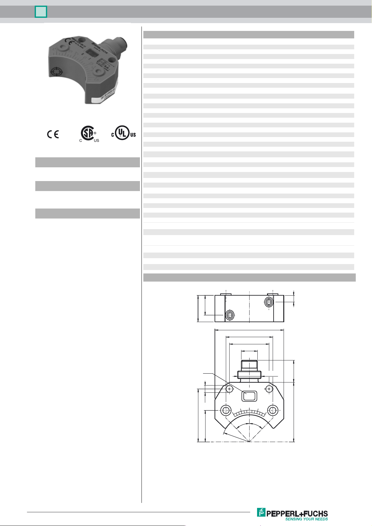
Dimensions
15
20
3 mm
n
2.6 ... 2.6 mm typ.
r
≤ 3 V
d
0 ... 200 mA
L
0 ... 0.5 mA typ. 0.1 µA at 25 °C
r
≤ 25 mA
0
≤ 500 ms
v
EN 60947-5-2:2007
IEC 60947-5-2:2007
5
Release date: 2016-02-11 17:19 Date of issue: 2016-02-11 038141_eng.xml
Refer to “General Notes Relating to Pepperl+Fuchs Product Information”.
52
35.4
30
M12x1
LED
M18x1
ø5.3
40
45°
45°
23.75
R20.8
45 17
1
Inductive sensor NBN3-F25F-E8-V1
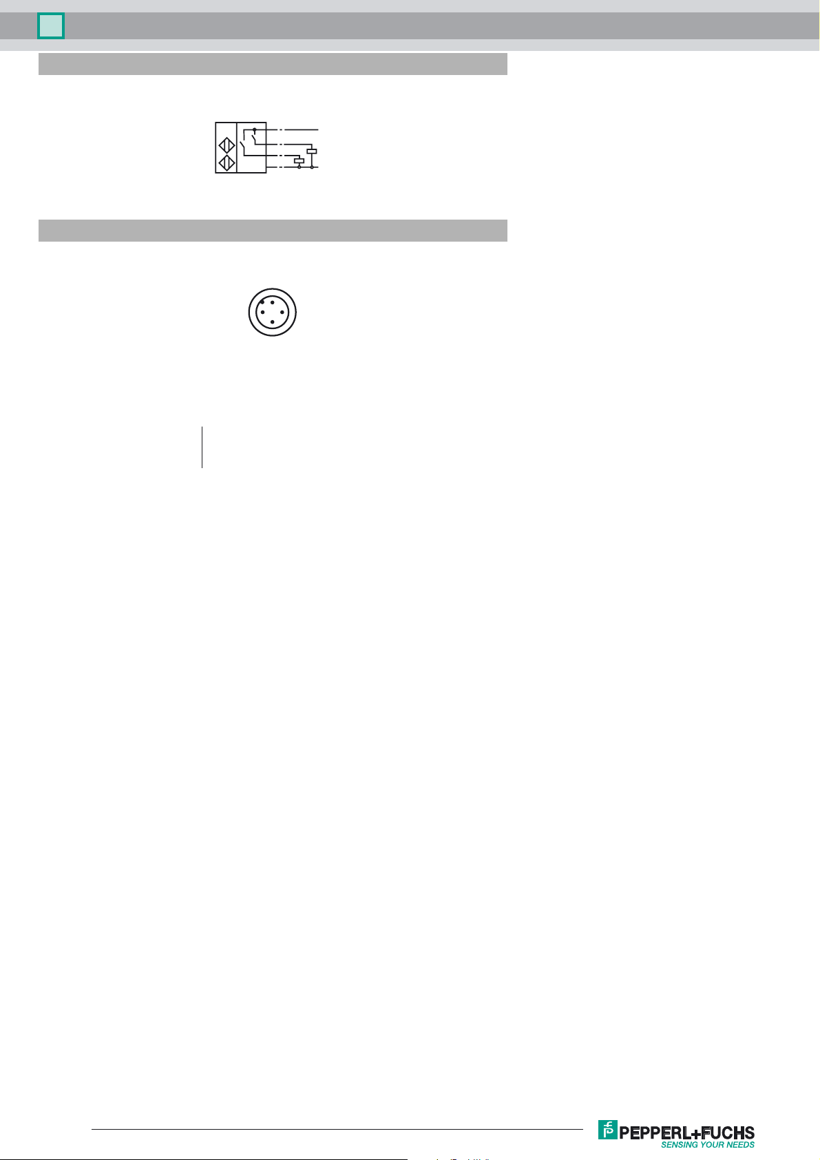
Electrical Connection
E8
Pinout
I
I
II
1 / BN
I
4 / BK
II
2 / WH
3 / BU
1
L+
L-
2
Wire colors in accordance with EN 60947-5-2
1 BN
2 WH
3 BU
4 BK
(brown)
(white)
(blue)
(black)
4
3
Release date: 2016-02-11 17:19 Date of issue: 2016-02-11 038141_eng.xml
Refer to “General Notes Relating to Pepperl+Fuchs Product Information”.
2
 Loading...