

Inductive power clamp sensor NBN2-F581-160S6-E10-V1
Technical Data
General specifications
Switching function 2 x normally open (NO)
Output type NPN
Rated operating distance sn2 mm
Installation non-flush
Output polarity DC
Model Number
NBN2-F581-160S6-E10-V1
Features
•Basic series
• Extremely bright triple luminous band
indication
• M12 plug with safety screw assembly
adjustable in 45° grid
• For use in direct- and alternating-field
welding systems
• Completely halogen and silicon free
Assured operating distance s
Reduction factor rAl 0.35
Reduction factor r
Reduction factor r
Output type 4-wire
Nominal ratings
Operating voltage UB10 ... 30 V DC
Switching frequency f 0 ... 25 Hz
Hysteresis H 3 ... 20 % 5 typ.
Reverse polarity protection yes
Short-circuit protection pulsing
Voltage drop U
Operating current I
Off-state current I
No-load supply current I
Constant magnetic field B 100 mT
Alternating magnetic field B 100 mT
Operating voltage indicator LED green
Switching state indicator switching state "close" = LED red (S2)
Functional safety related parameters
MTTFd 1445 a
Mission Time (TM) 20 a
Diagnostic Coverage (DC) 0 %
Ambient conditions
Ambient temperature -25 ... 70 °C (-13 ... 158 °F)
Storage temperature -40 ... 85 °C (-40 ... 185 °F)
Mechanical specifications
Connection type Connector plug M12 x 1 , 4-pin
Flexible lead, housing-sensor 160 mm ± 5 mm , PUR (halogen-free)
Housing material amplifier; PBT, PA6 + GD-ZN AL4
Degree of protection IP67
Compliance with standards and
directives
Standard conformity
Standards
Approvals and certificates
UL approval UL Recognized
CCC approval CCC approval / marking not required for products rated ≤36 V
0.3
Cu
0.7
304
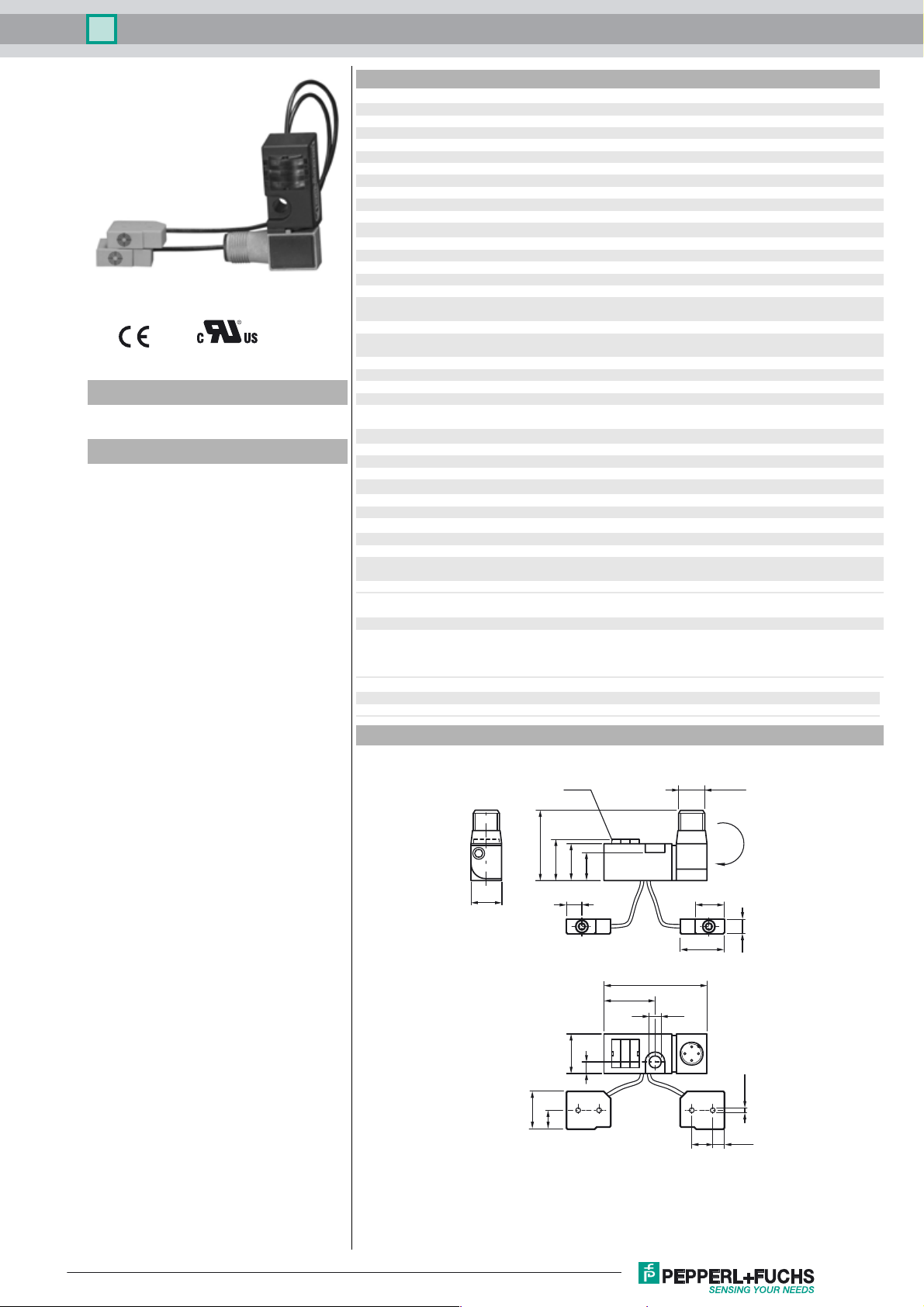
Dimensions
0 ... 1.62 mm
a
d
≤ 3 V DC
0 ... 100 mA
L
r
≤ 10 µA
≤ 35 mA
0
switching state "open" = LED yellow (S1)
oscillators; PBT
EN 60947-5-2:2007
EN 60947-5-2/A1:2012
IEC 60947-5-2:2007
IEC 60947-5-2 AMD 1:2012
137
20
M12 x 1
0°
(45°,
90°)
6.5
LEDs
YEGNRD
35
20
18
14
18
-0.2
47
23.5
5.3
18
5
Ø 2.2
17.2
8.6
9.5 5.25
Release date: 2018-08-02 12:33 Date of issue: 2018-08-02 801314_eng.xml
Refer to “General Notes Relating to Pepperl+Fuchs Product Information”.
1
Inductive power clamp sensor NBN2-F581-160S6-E10-V1
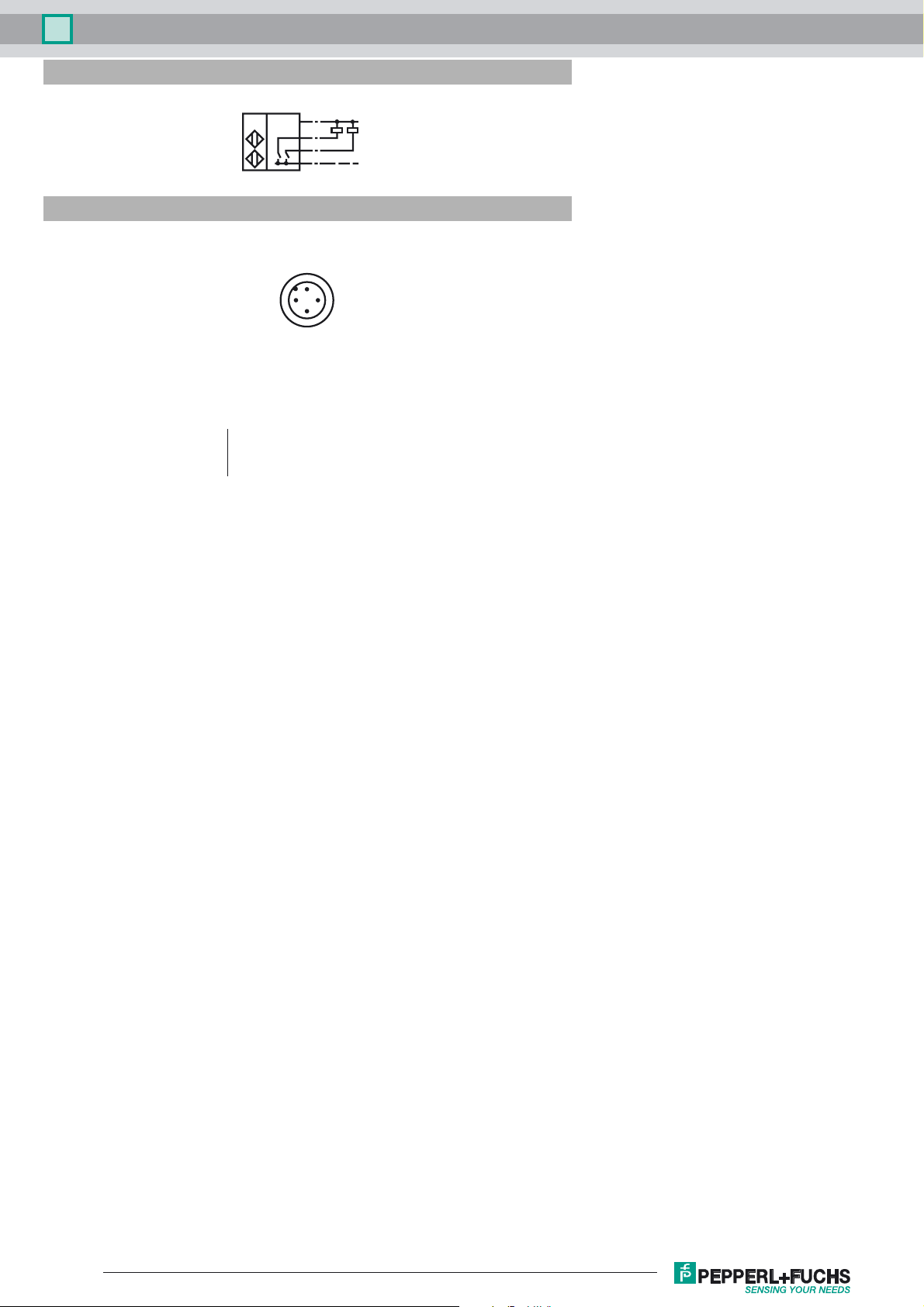
Electrical Connection
E10
Pinout
I
O
C
1/BN
4/BK
2/WH
O
C
3/BU
1
L+
L-
2
Wire colors in accordance with EN 60947-5-2
1 BN
2 WH
3 BU
4 BK
(brown)
(white)
(blue)
(black)
4
3
Release date: 2018-08-02 12:33 Date of issue: 2018-08-02 801314_eng.xml
Refer to “General Notes Relating to Pepperl+Fuchs Product Information”.
2
 Loading...