

Inductive sensor NBN2-8GM40-E2-V3
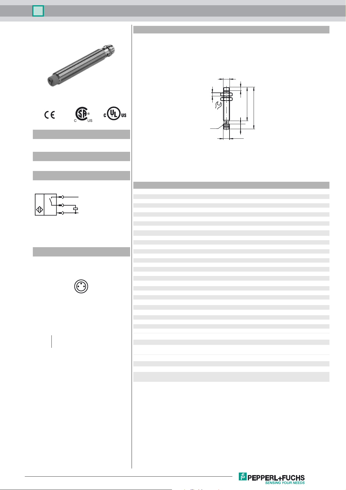
Dimensions
M8 x 1
Model Number
NBN2-8GM40-E2-V3
Features
• 2 mm non-flush
Connection
1
4
3
L+
L-
Pinout
4
13
Wire colors in accordance with EN 60947-5-2
1 BN
3 BU
4 BK
(brown)
(blue)
(black)
4
13
LED
M8 x 1
4
41
50
6
Technical Data
General specifications
Switching element function PNP NO
Rated operating distance s
Installation non-flush
Output polarity DC
Assured operating distance sa0 ... 1.62 mm
Reduction factor r
Reduction factor rCu 0.35
Reduction factor r
Nominal ratings
Operating voltage UB10 ... 30 V
Switching frequency f 0 ... 2000 Hz
Hysteresis H typ. 5%
Reverse polarity protected reverse polarity protected
Short-circuit protection pulsing
Voltage drop Ud≤ 1. 5 V
Operating current I
Off-state current I
No-load supply current I
Indication of the switching state Multihole-LED, yellow
Functional safety related parameters
MTTFd 3970 a
Mission Time (T
Diagnostic Coverage (DC) 0 %
Ambient conditions
Ambient temperature -25 ... 70 °C (-13 ... 158 °F)
Mechanical specifications
Connection type Device connector M8 x 1 , 3-pin
Housing material brass, nickel-plated
Sensing face PBT
Protection degree IP67
Compliance with standards and directives
Standard conformity
Standards
Approvals and certificates
UL approval cULus Listed, General Purpose
CSA approval cCSAus Listed, General Purpose
CCC approval Products with a maximum operating voltage of ≤36 V do not bear a
0.45
Al
0.7
304
) 20 a
M
2 mm
n
0 ... 100 mA
L
0 ... 0.5 mA typ. 0.1 µA at 25 °C
r
≤ 10 mA
0
EN 60947-5-2:2007
IEC 60947-5-2:2007
CCC marking because they do not require approval.
Release date: 2012-05-11 09:52 Date of issue: 2012-05-11 197154_eng.xml
Subject to modifications without notice
Copyright Pepperl+Fuchs
1
 Loading...