

Pepperl Fuchs NBN15-30GM50-E2-C-V1 Data Sheet
Inductive sensor NBN15-30GM50-E2-C-V1
Technical Data
General specifications
Switching element function PNP NO
Model Number
NBN15-30GM50-E2-C-V1
Features
• 15 mm non-flush
•3-wire DC
• Weld Immune
Accessories
BF 30
Mounting flange, 30 mm
V1-G
Female connector, M12, 4-pin, field attachable
V1-W
Female connector, M12, 4-pin, field attachable
V1-G-OR2M-POC
Female cordset, M12, 4-pin, TPE cable, welding-bead resistant
V1-W-OR2M-POC
Female cordset, M12, 4-pin, TPE cable, welding-bead resistant
Rated operating distance s
Installation non-flush
Output polarity DC
Assured operating distance sa0 ... 12.5 mm
Reduction factor r
Reduction factor rCu 0.2
Reduction factor r
Nominal ratings
Operating voltage UB10 ... 30 V DC
Switching frequency f 0 ... 10 Hz
Hysteresis H typ. 5 %
Reverse polarity protection reverse polarity protected
Short-circuit protection pulsing
Vol tag e d rop Ud≤ 3 V
Operating current I
Off-state current I
No-load supply current I
Time delay before availability t
Switching state indicator Multihole-LED, yellow
Mag. Field strength, AC fields 100 mT
Mag. Field strength, DC fields 100 mT
Ambient conditions
Ambient temperature -25 ... 70 °C (-13 ... 158 °F)
Mechanical specifications
Connection type Connector M12 x 1 , 4-pin
Housing material Brass, PTFE coated
Sensing face PPS
Degree of protection IP67
Compliance with standards and directives
Stan dard conf ormit y
Sta ndar ds
Approvals and certificates
UL approval cULus Listed, General Purpose
CSA approval cCSAus Listed, General Purpose
CCC approval CCC approval / marking not required for products rated ≤36 V
0.3
Al
0.6
304
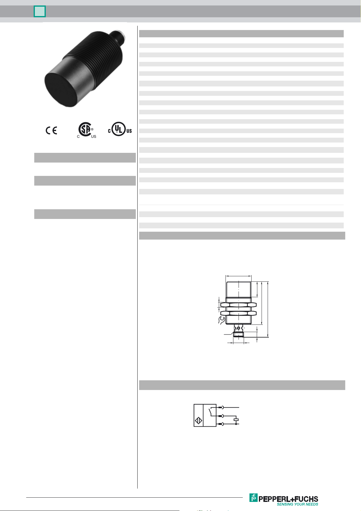
Dimensions
15 mm
n
0 ... 200 mA
L
0 ... 0.5 mA typ. 0.1 µA at 25 °C
r
≤ 15 mA
0
≤ 30 ms
v
EN 60947-5-2:2007
IEC 60947-5-2:2007
M30x1,5
Electrical Connection
18
5
36
LED
M12x1
1
L+
50
65
6
4
3
L-
Release date: 2015-02-17 15:14 Date of issue: 2015-02-17 906352_eng.xml
Refer to “General Notes Relating to Pepperl+Fuchs Product Information”.
1
Inductive sensor NBN15-30GM50-E2-C-V1
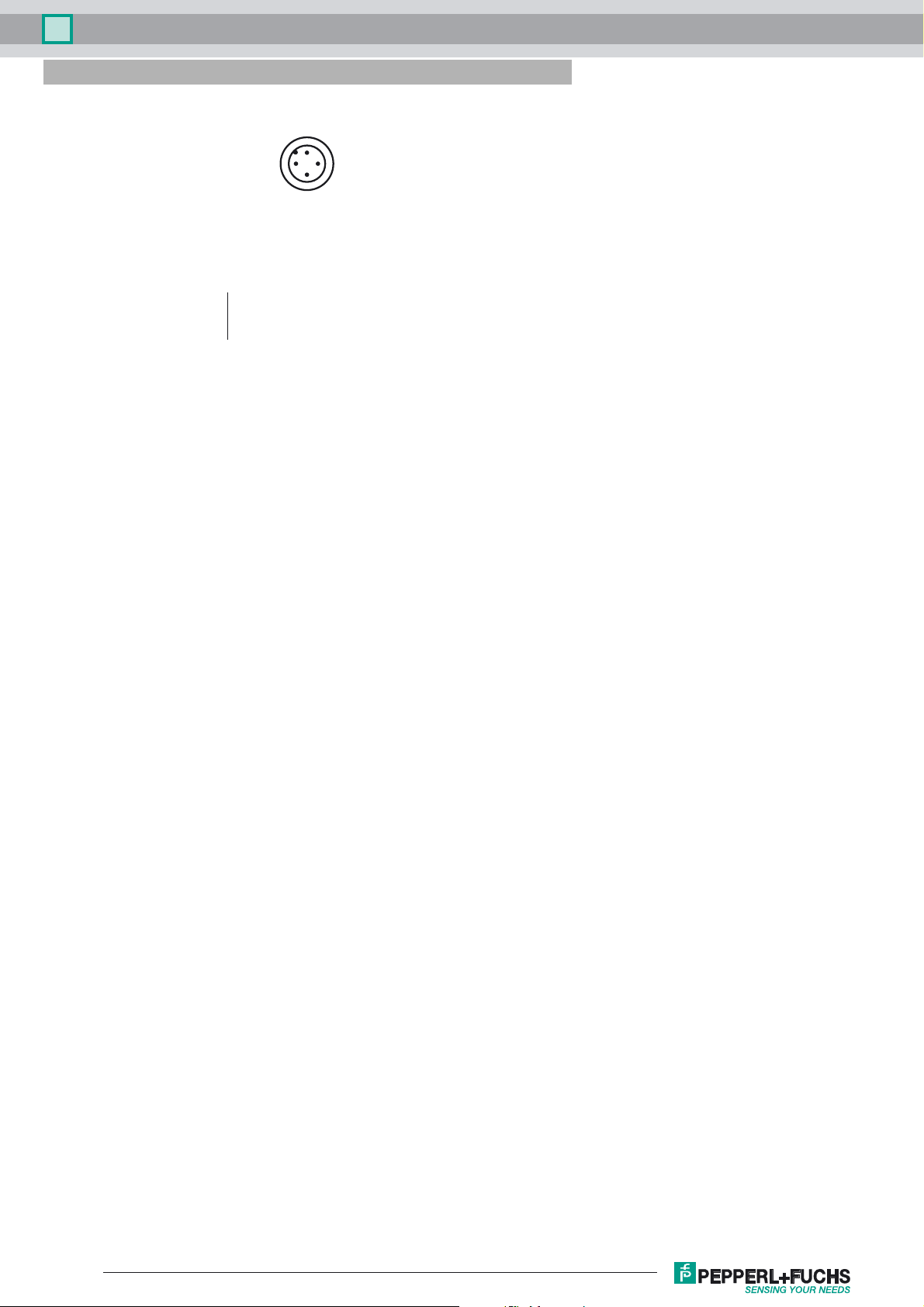
Pinout
1
2
Wire colors in accordance with EN 60947-5-2
1 BN
2 WH
3 BU
4 BK
(brown)
(white)
(blue)
(black)
4
3
Release date: 2015-02-17 15:14 Date of issue: 2015-02-17 906352_eng.xml
Refer to “General Notes Relating to Pepperl+Fuchs Product Information”.
2
 Loading...