

Inductive sensor NBB6-F-B3
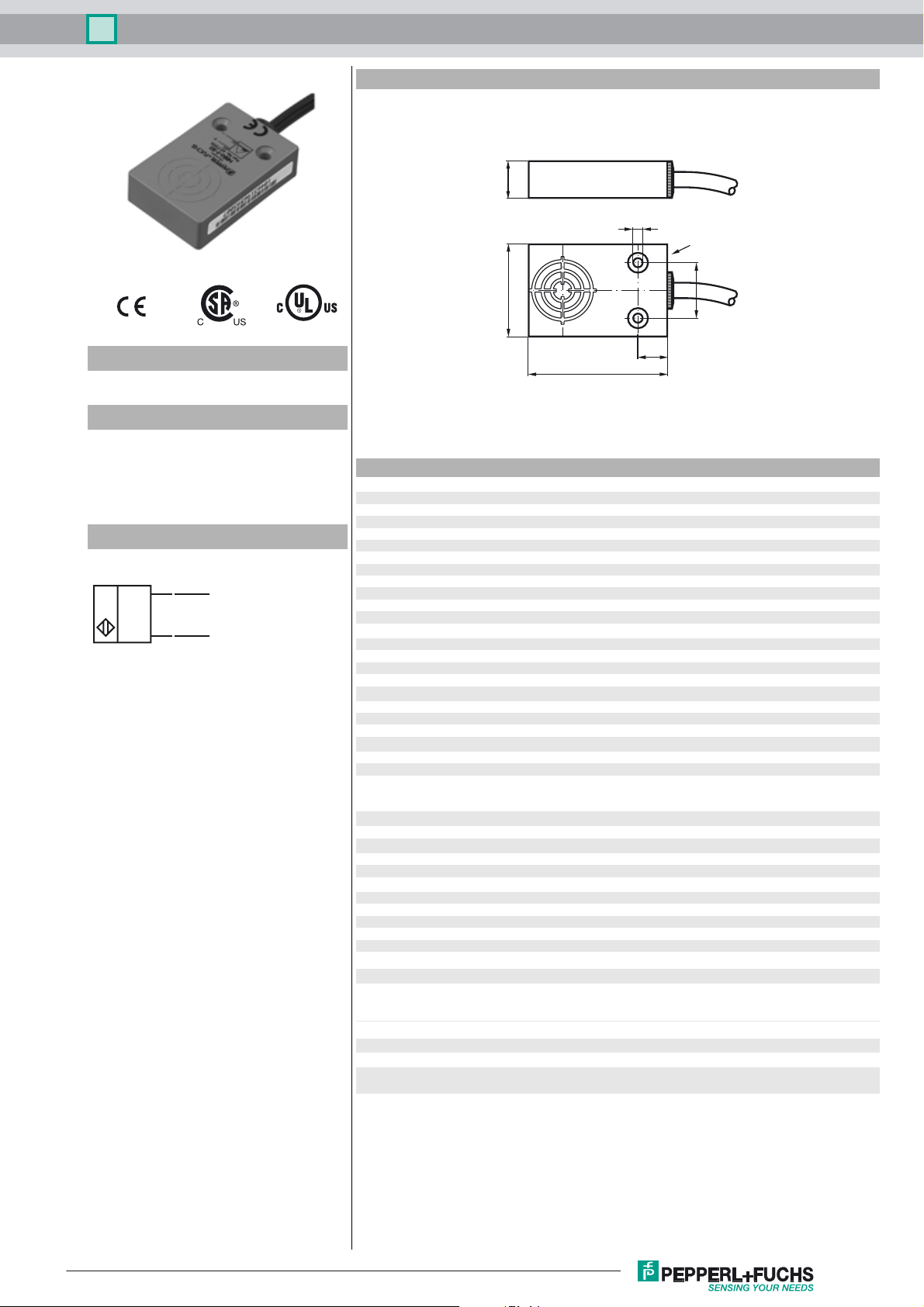
Dimensions
12
3,2
LED
Model Number
NBB6-F-B3
Features
• Basic series
•6 mm flush
• NO/NC selectable
• Protection degree IP67
• Oscillator monitoring
Connection
BN
BU
(+)
(-)
30
9,5
45
18
Technical Data
General specifications
Switching element function NO/NC programmable
Rated operating distance s
Installation flush
Output polarity AS-Interface
Assured operating distance sa0 ... 4.86 mm
Reduction factor r
Reduction factor rCu 0.25
Reduction factor r
Slave type Standard slave
AS-Interface specification V2.1
Required master specification ≥ V2.1
Nominal ratings
Operating voltage UB26.5 ... 31.9 V via AS-i bus system
Switching frequency f ≥ 500 (P3=0),
Hysteresis H typ. 5 %
Operating current I
Functional safety related parameters
MTTFd 1873 a
Mission Time (TM) 20 a
Diagnostic Coverage (DC) 0 %
Indicators/operating means
LED POWER AS-Interface voltage; LED green
LED IN switching state (input); LED yellow
LED OUT Dual LED yellow/red
Electrical specifications
Rated operational voltage Ue26.5 ... 31.6 V from AS-Interface
Ambient conditions
Ambient temperature -25 ... 70 °C (-13 ... 158 °F)
Storage temperature -40 ... 85 °C (-40 ... 185 °F)
Mechanical specifications
Connection type cable PVC , 2 m
Core cross-section 0.34 mm
Housing material PBT
Protection degree IP67
Mass 90 g
Compliance with standards and directives
Standard conformity
Standards
Approvals and certificates
UL approval cULus Listed, General Purpose
CSA approval cCSAus Listed, General Purpose
CCC approval Products with a maximum operating voltage of ≤36 V do not bear a
0.28
Al
0.75
304
6 mm
n
20 mA
L
yellow: switching state
red: error mode
2
EN 60947-5-2:2007
IEC 60947-5-2:2007
EN 50295:1999
CCC marking because they do not require approval.
Release date: 2012-05-23 10:20 Date of issue: 2012-05-23 190763_eng.xml
Subject to modifications without notice
Copyright Pepperl+Fuchs
1

Inductive sensor NBB6-F-B3
Programming instructions
Address 00 preset, alterable via
Busmaster or
programming units
IO-code 1
ID-code 1
ID1-code F
ID2-code F
Data bit
Bit Function
D0 switching state
D1 not used
D2 oscillator monitoring
D3 not used
Parameterbit
Bit Function
P0 not used
P1 switching element function
NO* / NC
P2 not used
P3 not used
* Standard setting
Fault mode
- No communication
Red LED On
Green LED On
- Address ø set
Red LED On
Green LED flashes
Release date: 2012-05-23 10:20 Date of issue: 2012-05-23 190763_eng.xml
Subject to modifications without notice
Copyright Pepperl+Fuchs
2
 Loading...