

Pepperl Fuchs NBB5-18GM40-E0-V1 Data Sheet
Inductive sensor NBB5-18GM40-E0-V1
Technical Data
General specifications
Switching function Normally open (NO)
Output type NPN
Rated operating distance sn5 mm
Installation flush
Output polarity DC
Model Number
NBB5-18GM40-E0-V1
Features
•Basic series
•5 mm flush
Accessories
BF 18
Mounting flange, 18 mm
V1-W
Female connector, M12, 4-pin, field attachable
V1-G
Female connector, M12, 4-pin, field attachable
V1-G-2M-PUR
Female cordset, M12, 4-pin, PUR cable
V1-W-2M-PUR
Female cordset, M12, 4-pin, PUR cable
EXG-18
Quick mounting bracket with dead stop
Assured operating distance s
Reduction factor rAl 0.3
Reduction factor r
Reduction factor r
Output type 3-wire
Nominal ratings
Operating voltage UB10 ... 30 V
Switching frequency f 0 ... 1000 Hz
Hysteresis H 3 ... 10 %
Reverse polarity protection reverse polarity protected
Short-circuit protection pulsing
Voltage drop Ud≤ 3 V
Operating current I
Off-state current I
No-load supply current I
Switching state indicator LED, yellow
Functional safety related parameters
MTTFd 2010 a
Mission Time (T
Diagnostic Coverage (DC) 0 %
Indicators/operating means
Operation indicator LED yellow
Ambient conditions
Ambient temperature -25 ... 70 °C (-13 ... 158 °F)
Mechanical specifications
Connection type Connector M12 x 1 , 4-pin
Housing material brass, nickel-plated
Sensing face PBT
Degree of protection IP67
Compliance with standards and
directives
Standard conformity
Standards
Approvals and certificates
UL approval cULus Listed, General Purpose
CSA approval cCSAus Listed, General Purpose
CCC approval CCC approval / marking not required for products rated ≤36 V
0.25
Cu
0.7
304
) 20 a
M
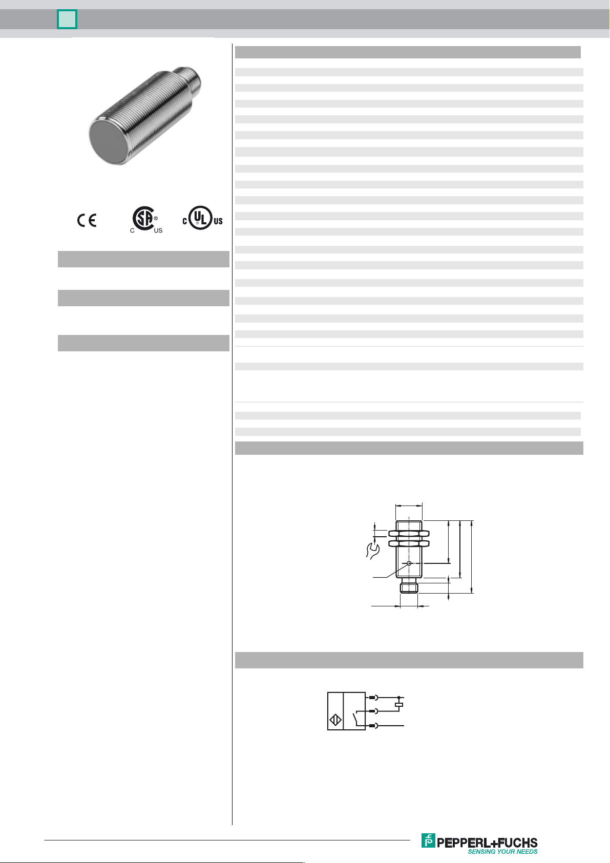
Dimensions
0 ... 4.05 mm
a
0 ... 100 mA
L
≤ 0.5 mA
r
≤ 15 mA
0
EN 60947-5-2:2007
EN 60947-5-2/A1:2012
IEC 60947-5-2:2007
IEC 60947-5-2 AMD 1:2012
Electrical Connection
4
24
LED
M12 x 1
1
4
3
M18 x 1
L+
L-
29.57
39
50
Release date: 2017-07-11 13:59 Date of issue: 2017-07-11 083417_eng.xml
Refer to “General Notes Relating to Pepperl+Fuchs Product Information”.
1
Inductive sensor NBB5-18GM40-E0-V1
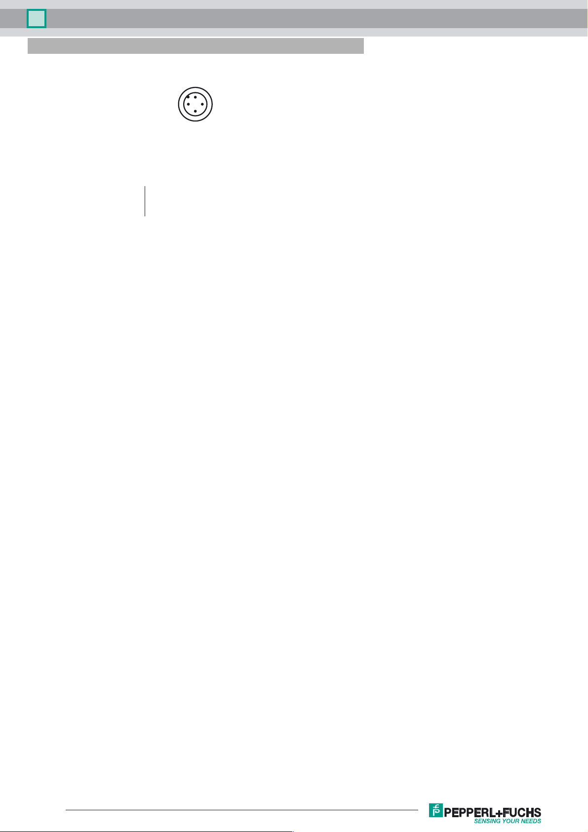
Pinout
1
2
Wire colors in accordance with EN 60947-5-2
1 BN
2 WH
3 BU
4 BK
(brown)
(white)
(blue)
(black)
4
3
Release date: 2017-07-11 13:59 Date of issue: 2017-07-11 083417_eng.xml
Refer to “General Notes Relating to Pepperl+Fuchs Product Information”.
2
 Loading...