

Inductive sensor NBB4-12GM50-E2-V1-3G-3D
Technical Data
General specifications
Switching function Normally open (NO)
Output type PNP
Rated operating distance sn4 mm
Installation flush
Output polarity DC
Model Number
NBB4-12GM50-E2-V1-3G-3D
Features
• Increased operating distance
•4 mm flush
• ATEX-approval for zone 2 and zone 22
Accessories
BF 12
Mounting flange, 12 mm
EXG-12
Quick mounting bracket with dead stop
Assured operating distance s
Reduction factor rAl 0.45
Reduction factor r
Reduction factor r
Nominal ratings
Operating voltage UB10 ... 30 V DC
Switching frequency f 0 ... 1000 Hz
Hysteresis H typ. 5 %
Reverse polarity protection reverse polarity protected
Short-circuit protection pulsing
Vol tag e d rop U
Operating current I
Off-state current I
Off-state current TU =40 °C, switching ele-
ment off
No-load supply current I
Time delay before availability t
Switching state indicator Multihole-LED, yellow
Functional safety related parameters
MTTFd 1820 a
Mission Time (TM) 20 a
Diagnostic Coverage (DC) 0 %
Ambient conditions
Ambient temperature -25 ... 70 °C (-13 ... 158 °F)
Mechanical specifications
Connection type Connector M12 x 1 , 4-pin
Cable version PBT
Housing material brass, nickel-plated
Sensing face PBT
Degree of protection IP67
General information
Use in the hazardous area see instruction manuals
Category
Compliance with standards and directives
Stan dard conf ormit y
Sta ndar ds
Approvals and certificates
UL approval cULus Listed, General Purpose
CSA approval cCSAus Listed, General Purpose
CCC approval CCC approval / marking not required for products rated ≤36 V
0.35
Cu
0.7
304
0 ... 3.24 mm
a
≤ 3 V
d
0 ... 150 mA
L
0 ... 0.5 mA typ. 0.1 µA at 25 °C
r
≤
≤ 15 mA
0
≤ 5 ms
v
3G; 3D
EN 60947-5-2:2007
IEC 60947-5-2:2007
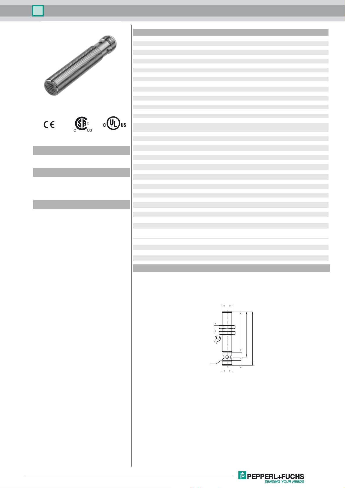
Dimensions
17
LED
M12x1
4
M12x1
49
55
65
6
Release date: 2016-11-07 10:11 Date of issue: 2016-11-07 212426_eng.xml
Refer to “General Notes Relating to Pepperl+Fuchs Product Information”.
1
Inductive sensor NBB4-12GM50-E2-V1-3G-3D
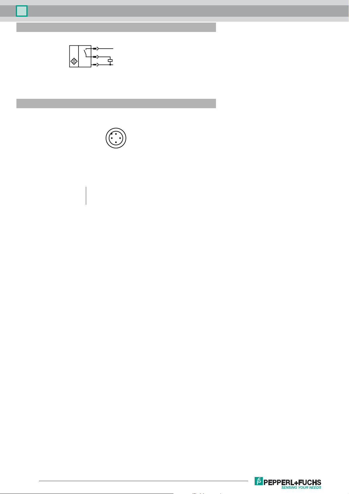
Electrical Connection
Pinout
1
4
3
Wire colors in accordance with EN 60947-5-2
1 BN
2 WH
3 BU
4 BK
2
L+
L-
1
4
3
(brown)
(white)
(blue)
(black)
Release date: 2016-11-07 10:11 Date of issue: 2016-11-07 212426_eng.xml
Refer to “General Notes Relating to Pepperl+Fuchs Product Information”.
2
 Loading...