

Pepperl Fuchs NBB4-12GM50-E2 Data Sheet
Inductive sensor NBB4-12GM50-E2
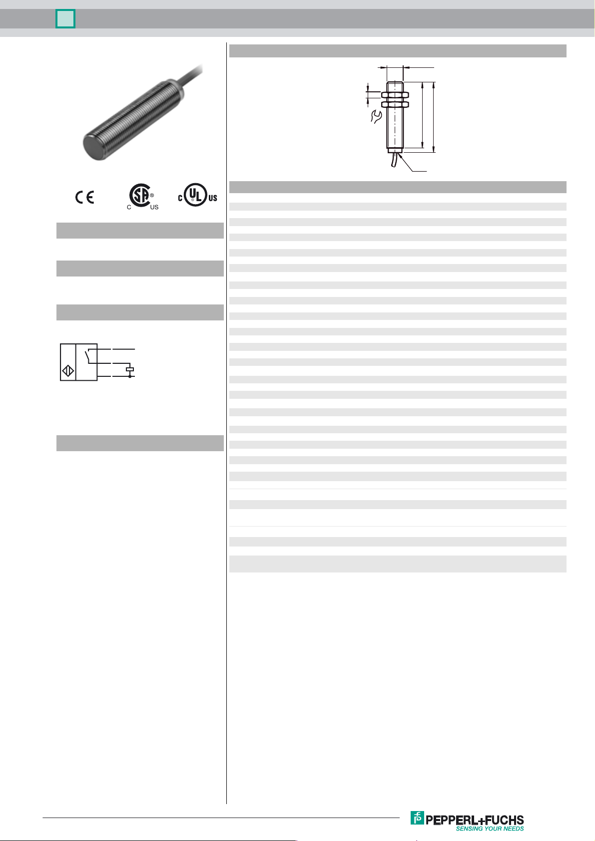
Dimensions
M12 x 1
4
47
50
LED
2
Model Number
NBB4-12GM50-E2
Features
•4 mm flush
• Increased operating distance
Connection
BN
BK
BU
L+
L-
Accessories
BF 12
Mounting flange, 12 mm
EXG-12
Quick mounting bracket with dead stop
17
Technical Data
General specifications
Switching element function PNP NO
Rated operating distance s
Installation flush
Output polarity DC
Assured operating distance sa0 ... 3.24 mm
Reduction factor r
Reduction factor rCu 0.35
Reduction factor r
Reduction factor r
Nominal ratings
Operating voltage UB10 ... 30 V
Switching frequency f 0 ... 800 Hz
Hysteresis H typ. 5%
Reverse polarity protection reverse polarity protected
Short-circuit protection pulsing
Voltage drop U
Operating current I
Off-state current I
No-load supply current I
Time delay before availability t
Indication of the switching state LED, yellow
Functional safety related parameters
MTTFd 1820 a
Mission Time (T
Diagnostic Coverage (DC) 0 %
Ambient conditions
Ambient temperature -25 ... 70 °C (-13 ... 158 °F)
Mechanical specifications
Connection type cable PVC , 2 m
Cable version 3 x 0.14 mm
Core cross-section 0.14 mm
Housing material brass, nickel-plated
Sensing face PBT
Protection degree IP67
General information
Scope of delivery 2 self locking nuts in scope of delivery
Compliance with standards and directives
Standard conformity
Standards
Approvals and certificates
UL approval cULus Listed, General Purpose
CSA approval cCSAus Listed, General Purpose
CCC approval Products with a maximum operating voltage of ≤36 V do not bear a
0.39
Al
0.75
304
0.49
Brass
) 20 a
M
4 mm
n
≤ 3 V
d
0 ... 200 mA
L
0 ... 0.5 mA typ. 0.1 µA at 25 °C
r
≤ 15 mA
0
≤ 5 ms
v
2
EN 60947-5-2:2007
IEC 60947-5-2:2007
CCC marking because they do not require approval.
Release date: 2012-08-30 11:20 Date of issue: 2012-08-30 800734_eng.xml
Subject to modifications without notice
Copyright Pepperl+Fuchs
1
 Loading...