

Inductive sensor NBB20-U1-B3B
Technical Data
General specifications
Switching element function NO/NC programmable
Model Number
NBB20-U1-B3B
Features
• Sensor head bidirectional and rotatable
• 20 mm flush
• A/B slave with extended addressing
possibility for up to 62 slaves
• Adjustable sensor head
• NO/NC programmable
• Oscillator monitoring
• On/Off delay (disconnectable)
Accessories
V1-M20-80
Receptacles, M12/M20; plastic version
MHW 01
Modular mounting bracket
Rated operating distance s
Installation flush
Output polarity AS-Interface
Assured operating distance sa0 ... 16.2 mm
Actual operating distance s
Reduction factor rAl 0.4
Reduction factor r
Reduction factor r
Slave type A/B slave
AS-Interface specification V3.0
Required master specification ≥ V2.1
Nominal ratings
Operating voltage UB26.5 ... 31.9 V via AS-i bus system
Switching frequency f 0 ... 150 Hz
Hysteresis H 1 ... 15 typ. 5 %
Reverse polarity protection reverse polarity protected
No-load supply current I
Time delay before availability t
Operating voltage indicator LED, green
Switching state indicator LED, yellow
Error indicator LED, red
Functional safety related parameters
MTTFd 1330 a
Mission Time (TM) 20 a
Diagnostic Coverage (DC) 0 %
Ambient conditions
Ambient temperature -25 ... 70 °C (-13 ... 158 °F)
Storage temperature -40 ... 85 °C (-40 ... 185 °F)
Mechanical specifications
Connection type screw terminals
Information for connection A maximum of two conductors with the same core cross-section
Core cross-section up to 2.5 mm
Minimum core cross-section
Maximum core cross-section
Housing material PA/metal with epoxy powder coating
Sensing face PBT
Housing base plastic
Degree of protection IP68 / IP69K
Compliance with standards and directives
Stan dard conf ormit y
Sta ndar ds
Approvals and certificates
UL approval cULus Listed, General Purpose
CSA approval cCSAus Listed, General Purpose
CCC approval CCC approval / marking not required for products rated ≤36 V
0.35
Cu
0.85
304
20 mm
n
18 ... 22 mm typ. 20 mm
r
≤ 25 mA
0
≤ 1000 ms
v
may be mounted on one terminal connection!
tightening torque 1.2 Nm + 10 %
without wire end ferrule 0.5 mm
without wire end ferrule 2.5 mm2 , with connector sleeves 1.5 mm
EN 60947-5-2:2007
IEC 60947-5-2:2007
2
2
, with connector sleeves 0.34 mm
2
2
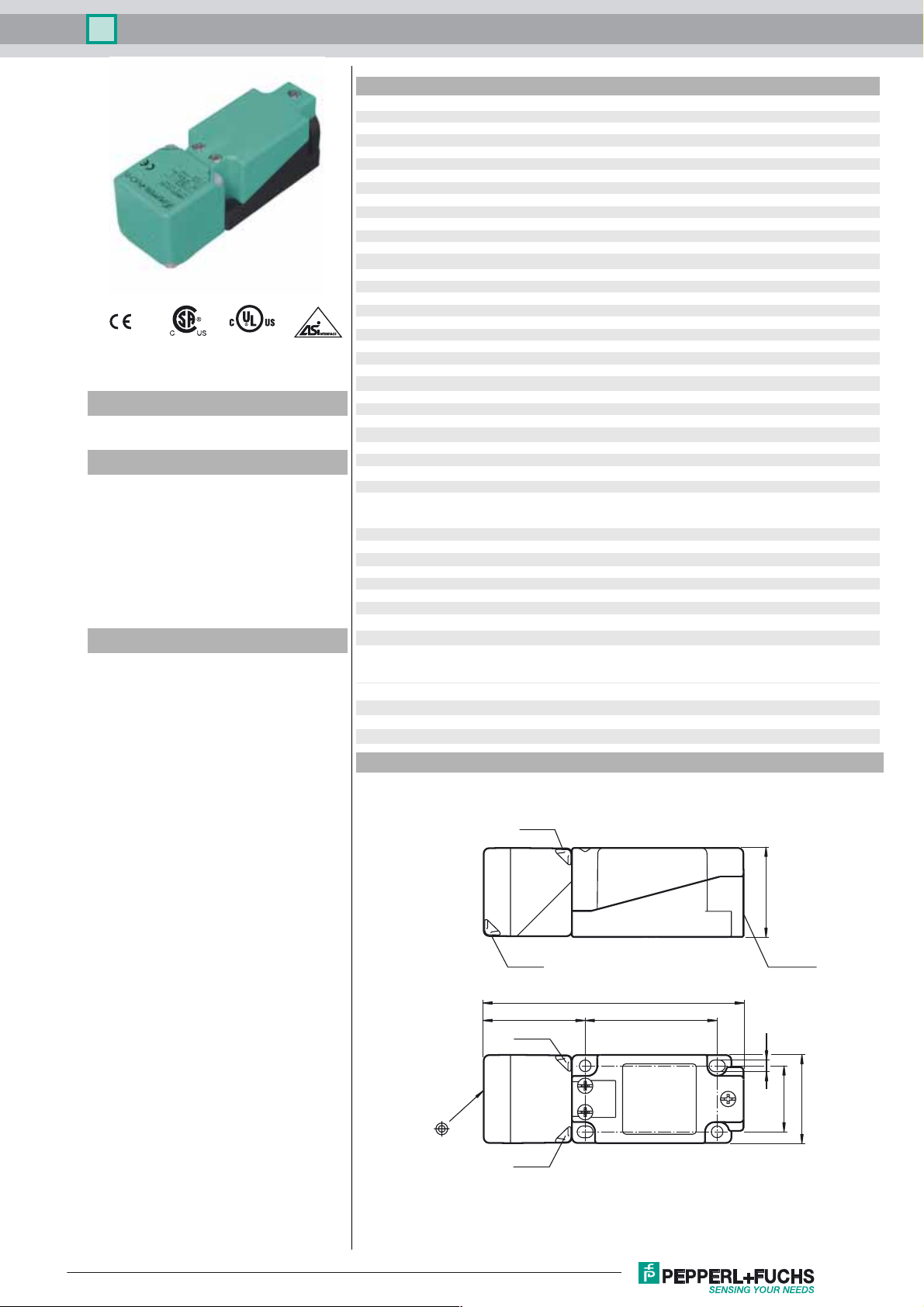
Dimensions
LED ye
LED gn
LED gn
LED ye
118
40
M20 x 1.5
6046
5.3
30
40
Release date: 2016-09-29 11:32 Date of issue: 2016-10-10 226315_eng.xml
Refer to “General Notes Relating to Pepperl+Fuchs Product Information”.
1
Inductive sensor NBB20-U1-B3B
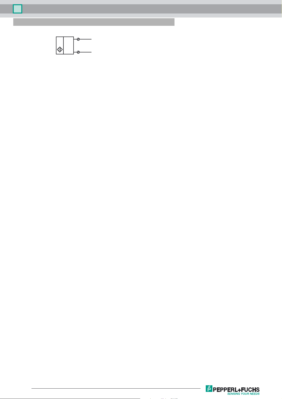
Electrical Connection
3
4
(+)
(-)
Programming Instructions
Adress 00 preset, alterable
via Busmaster
or programming units
IO-Code 0
ID-Code A
ID1-Code 7
ID2-Code E
Data bit
Bit Function
D0 switching state
1)
(0 = damped; 1 = undamped)
D1 not used
D2 oscillator monitoring
(0= oscillator defective,
1=normal operation)
D3 not used
Parameter bit
Bit Function
P0 ON / Off delay
activated* / deactivated
P1 switching element function2)
(0 = NC; 1 = NO)
P2 not used
P3 not used
1)
Applies to NO funktion (P1 = 1; preset),
with NC function (P1 = 0) reversed characteristics
2)
Default setting: NO
Release date: 2016-09-29 11:32 Date of issue: 2016-10-10 226315_eng.xml
Refer to “General Notes Relating to Pepperl+Fuchs Product Information”.
2

Inductive sensor NBB20-U1-B3B
Indication depending on the operation mode
Symptoms green LED
(POWER)
normal operation on off 1
Oscillator defect flashing flashing 0
no communication off on 1
On/off delay:
The on/off delay is preset and switched on (P0=1). On delay approx.15 ms, when P0=1 and NO function (P1=1). Off delay
approx.15 ms, when P0=1 and NC function (P1=0).
red LED
(FAULT)
Data bit
D2
Release date: 2016-09-29 11:32 Date of issue: 2016-10-10 226315_eng.xml
Refer to “General Notes Relating to Pepperl+Fuchs Product Information”.
3
 Loading...