

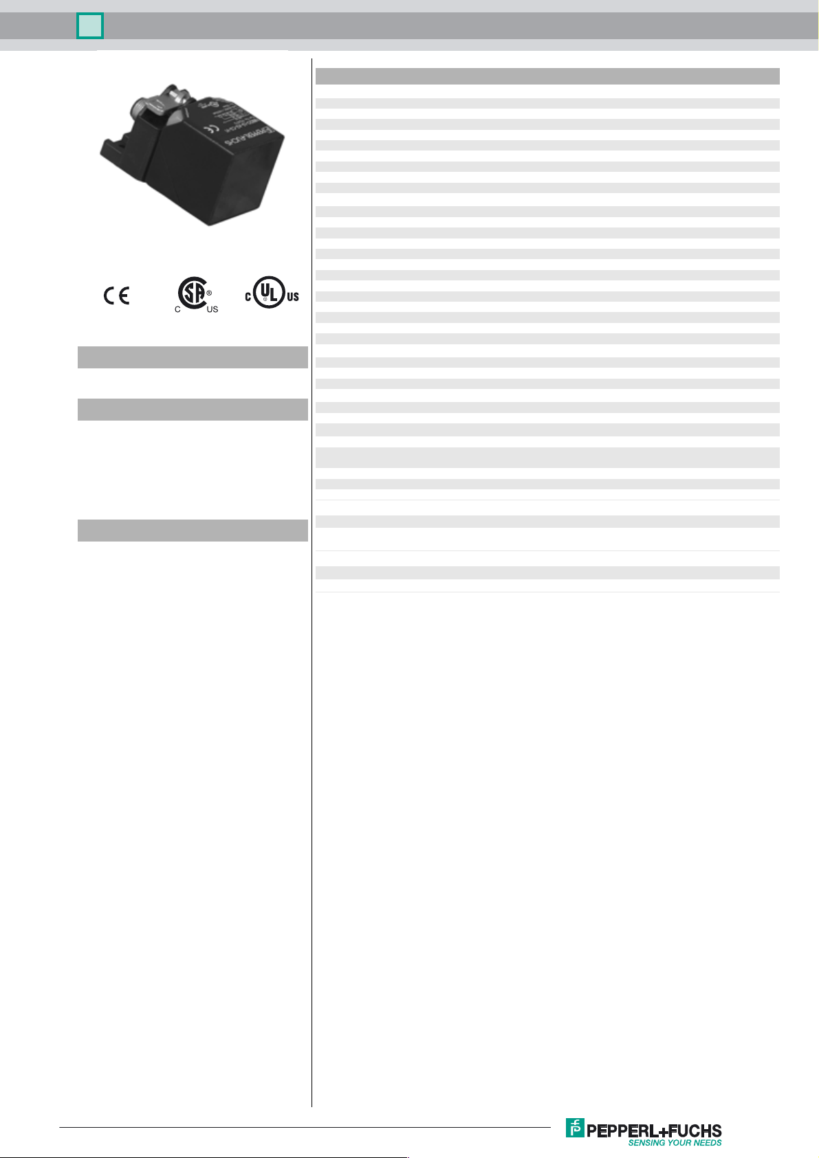
Inductive sensor NBB20-L3-A2-C3-V1
Technical Data
General specifications
Switching element function PNP NO/NC
Model Number
NBB20-L3-A2-C3-V1
Features
• 20 mm flush
•4-wire DC
• Weld Immune
• Quick mounting bracket
•2-way LED indicator
• Active surface thermoset
Accessories
V1-G-OR2M-POC
Female cordset, M12, 4-pin, TPE cable, welding-bead resistant
Rated operating distance s
Installation flush
Output polarity DC
Assured operating distance sa0 ... 16.2 mm
Reduction factor r
Reduction factor rCu 0.38
Reduction factor r
Reduction factor r
Nominal ratings
Operating voltage UB10 ... 30 V DC
Switching frequency f 0 ... 5 Hz
Hysteresis H typ. 5 %
Reverse polarity protection reverse polarity protected
Short-circuit protection pulsing
Vol tag e d rop U
Operating current I
Off-state current I
No-load supply current I
Time delay before availability t
Alternating magnetic field B 200 mT
Operating voltage indicator LED, green
Switching state indicator LED, yellow
Functional safety related parameters
MTTFd 1420 a
Mission Time (T
Diagnostic Coverage (DC) 0 %
Ambient conditions
Ambient temperature -25 ... 85 °C (-13 ... 185 °F)
Storage temperature -40 ... 85 °C (-40 ... 185 °F)
Mechanical specifications
Connection type Connector M12 x 1 , 4-pin
Housing material GD-ZnAl4Cu1, coated
Sensing face Thermoset Plastic
Housing base Zinc, PTFE coated
Degree of protection IP67
Compliance with standards and directives
Stan dard conf ormit y
Sta ndar ds
Approvals and certificates
UL approval cULus Listed, General Purpose
CSA approval cCSAus Listed, General Purpose
0.42
Al
0.75
304
0.49
Brass
) 20 a
M
20 mm
n
≤ 3 V
d
0 ... 200 mA
L
0 ... 0.5 mA
r
≤ 20 mA
0
80 ms
v
mounting flange PA6-GF35
EN 60947-5-2:2007
IEC 60947-5-2:2007
Release date: 2015-02-24 10:47 Date of issue: 2015-02-24 912476_eng.xml
Refer to “General Notes Relating to Pepperl+Fuchs Product Information”.
1
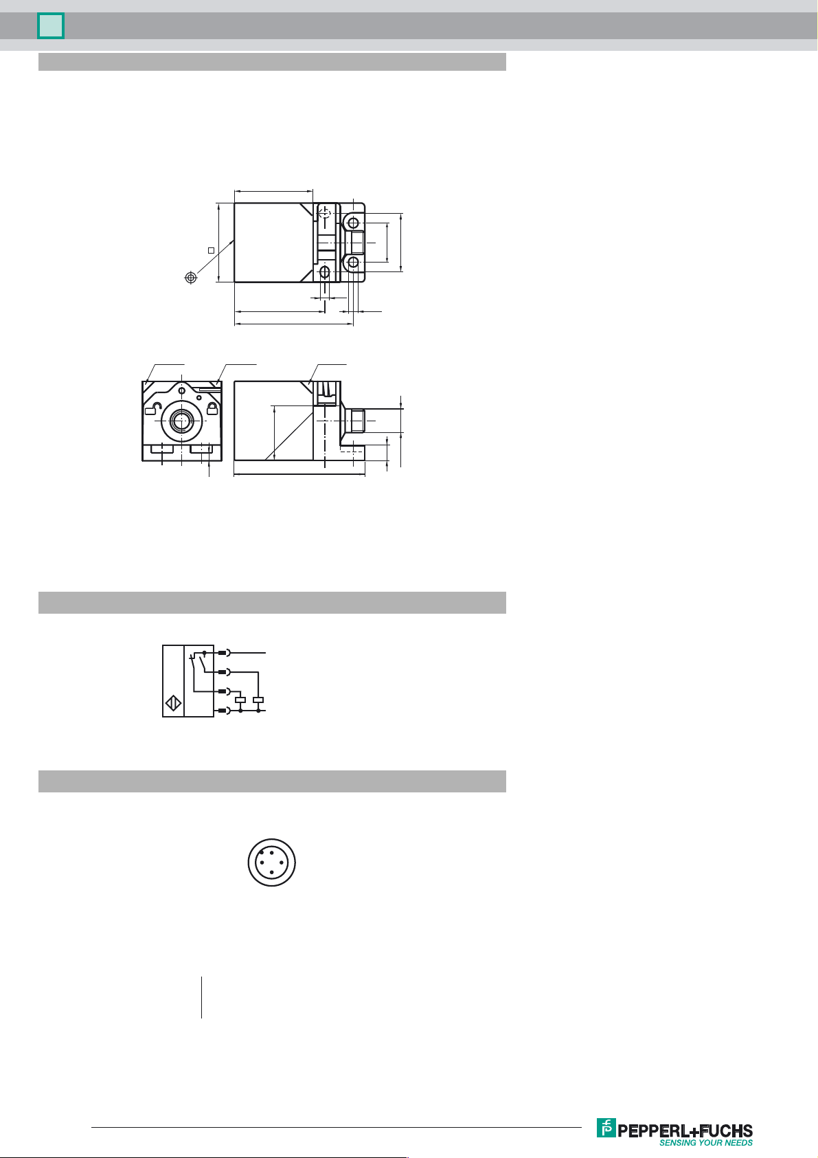
Inductive sensor NBB20-L3-A2-C3-V1
Dimensions
40
Electrical Connection
40
5.5
46
60
LED YELED GNLED YE
28
4
67
ø 5.5
20
7
30
M12 x 1
Pinout
1
4
2
3
Wire colors in accordance with EN 60947-5-2
1 BN
2 WH
3 BU
4 BK
2
L+
L-
1
4
3
(brown)
(white)
(blue)
(black)
Release date: 2015-02-24 10:47 Date of issue: 2015-02-24 912476_eng.xml
Refer to “General Notes Relating to Pepperl+Fuchs Product Information”.
2
 Loading...