

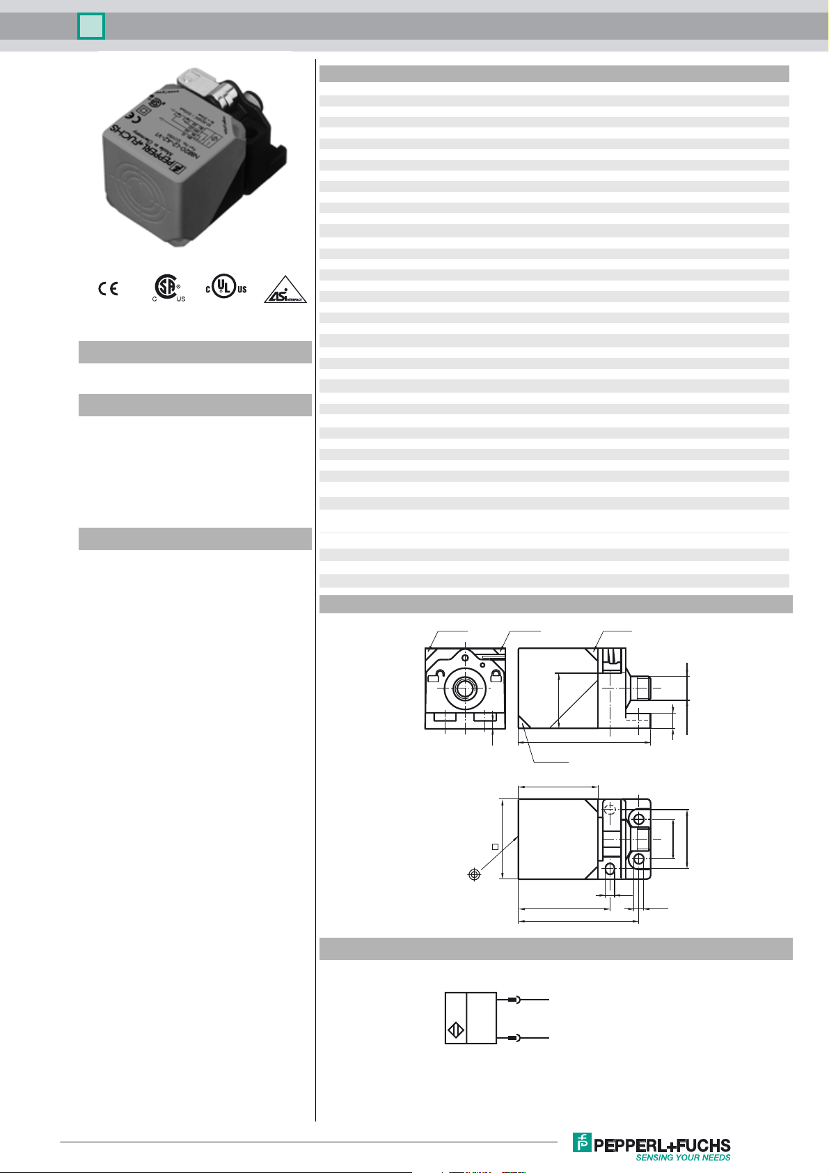
Inductive sensor NBB20-L2-B3-V1
Technical Data
General specifications
Switching element function NO/NC programmable
Model Number
NBB20-L2-B3-V1
Features
• Sensor head bidirectional and rotatable
•Basic series
• 20 mm flush
•NO/NC selectable
• Oscillator monitoring
• On/Off delay (disconnectable)
Accessories
V1-G
Female connector, M12, 4-pin, field attachable
V1-W
Female connector, M12, 4-pin, field attachable
V1-W-2M-PUR
Female cordset, M12, 4-pin, PUR cable
V1-G-2M-PUR
Female cordset, M12, 4-pin, PUR cable
MHW 01
Modular mounting bracket
MH 02-L
Mounting aid
Rated operating distance s
Installation flush
Output polarity AS-Interface
Assured operating distance sa0 ... 16.2 mm
Reduction factor r
Reduction factor rCu 0.31
Reduction factor r
Reduction factor r
Slave type Standard slave
AS-Interface specification V2.1
Required master specification ≥ V2.1
Nominal ratings
Operating voltage UB26.5 ... 31.9 V via AS-i bus system
Switching frequency f 0 ... 150 Hz
Hysteresis H typ. 5 %
Reverse polarity protection reverse polarity protected
No-load supply current I
Time delay before availability t
Operating voltage display LED, green
Switching state indication dual-LED, yellow
Fault indication dual-LED, red
Functional safety related parameters
MTTFd 1330 a
Mission Time (TM) 20 a
Diagnostic Coverage (DC) 0 %
Ambient conditions
Ambient temperature -25 ... 70 °C (-13 ... 158 °F)
Storage temperature -40 ... 85 °C (-40 ... 185 °F)
Mechanical specifications
Connection type Connector M12 x 1 , 4-pin
Housing material PA
Sensing face PA
Protection degree IP69K
Mass 130 g
Compliance with standards and directives
Stan dard conf ormit y
Sta ndar ds
Approvals and certificates
UL approval cULus Listed, General Purpose
CSA approval cCSAus Listed, General Purpose
CCC approval CCC approval / marking not required for products rated ≤36 V
0.33
Al
0.74
304
0.41
Brass
Dimensions
20 mm
n
≤ 40 mA
0
≤ 1000 ms
v
EN 60947-5-2:2007
IEC 60947-5-2:2007
4
28
LED gn
LED yeLED gnLED ye
7
67
M12 x 1
Release date: 2013-07-10 09:35 Date of issue: 2013-07-10 226317_eng.xml
Refer to “General Notes Relating to Pepperl+Fuchs Product Information”.
Electrical Connection
40
40
5.5
46
60
1
3
(+)
(-)
ø 5.5
30
20
1

Inductive sensor NBB20-L2-B3-V1
Pinout
1
2
4
3
Programming Instructions
Address 00 preset, alterable
via Busmaster or
programming units
IO-Code 1
ID-Code 1
ID1-Code F
ID2-Code F
Data bit
Bit Function
D0 switching state
1)
(0 = damped; 1 = undamped)
D1 not used
D2 oscillator monitoring
(0= oscillator defective,
1=normal operation)
D3 not used
Parameter bit
Bit Function
P0 ON / Off delay
activated* / deactivated
P1 switching element function2)
(0 = NC; 1 = NO)
P2 not used
P3 not used
1)
Applies to NO funktion (P1 = 1; preset),
with NC function (P1 = 0) reversed characteristics
2)
Default setting: NO
Release date: 2013-07-10 09:35 Date of issue: 2013-07-10 226317_eng.xml
Refer to “General Notes Relating to Pepperl+Fuchs Product Information”.
2
 Loading...