

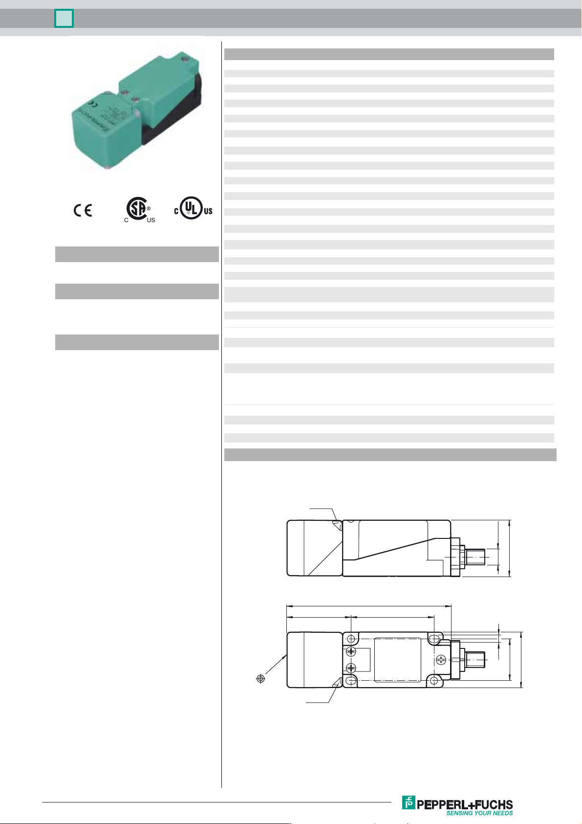
Inductive sensor NBB15-U4K-N0-V1
Technical Data
General specifications
Switching function Normally closed (NC)
Output type NAMUR
Rated operating distance sn15 mm
Installation flush
Assured operating distance sa0 ... 12.15 mm
Model Number
NBB15-U4K-N0-V1
Features
• Sensor head bidirectional and rotatable
• 15 mm flush
Accessories
MHW 01
Modular mounting bracket
V1-G-N-2M-PUR
Female cordset, M12, 2-pin, NAMUR, PUR cable
V1-W-N-2M-PUR
Female cordset, M12, 2-pin, NAMUR, PUR cable
V1-W
Female connector, M12, 4-pin, field attachable
V1-G
Female connector, M12, 4-pin, field attachable
Actual operating distance s
Reduction factor rAl 0.33
Reduction factor r
Reduction factor r
Nominal ratings
Nominal voltage Uo8 V
Switching frequency f 0 ... 300 Hz
Hysteresis H typ. 5 %
Reverse polarity protection yes
Short-circuit protection yes
Current consumption
Measuring plate not detected
Measuring plate detected
Switching state indicator LED, yellow
Ambient conditions
Ambient temperature -25 ... 100 °C (-13 ... 212 °F)
Storage temperature -40 ... 100 °C (-40 ... 212 °F)
Mechanical specifications
Connection type Connector M12 x 1 , 4-pin
Housing material PA /m et a l
Sensing face PA
Degree of protection IP68 / IP69K
Mass 225 g
Note Tightening torque: 1.8 Nm (housing)
General information
Use in the hazardous area see instruction manuals
Category
Compliance with standards and directives
Stan dard conf ormit y
NAMUR
Electromagnetic compatibility
Sta ndar ds
Approvals and certificates
UL approval cULus Listed, General Purpose
CSA approval cCSAus Listed, General Purpose
CCC approval CCC approval / marking not required for products rated ≤36 V
0.31
Cu
0.74
304
13.5 ... 16.5 mm typ. 15 mm
r
≥ 2.2 mA
≤ 1 mA
1G; 2G; 3G
EN 60947-5-6:2000
IEC 60947-5-6:1999
NE 21:2007
EN 60947-5-2:2007
IEC 60947-5-2:2007
Dimensions
LED ye
LED ye
118
M12 x 1
40
6046
5.3
30
40
Release date: 2016-12-05 12:14 Date of issue: 2017-01-02 213831_eng.xml
Refer to “General Notes Relating to Pepperl+Fuchs Product Information”.
1
Inductive sensor NBB15-U4K-N0-V1
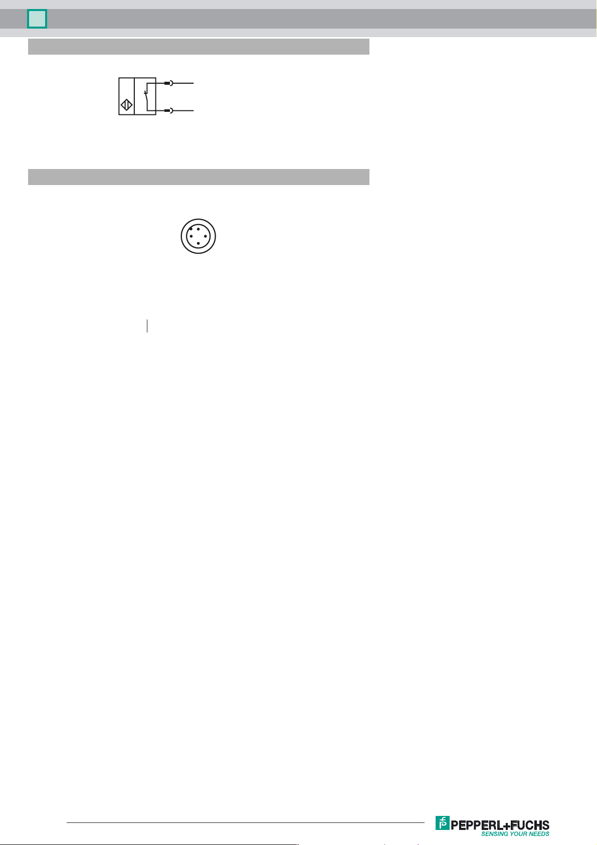
Electrical Connection
Pinout
1
2
Wire colors in accordance with EN 60947-5-6
1 BN
2 BU
2
L+
L-
1
4
3
(brown)
(blue)
Release date: 2016-12-05 12:14 Date of issue: 2017-01-02 213831_eng.xml
Refer to “General Notes Relating to Pepperl+Fuchs Product Information”.
2

Inductive sensor NBB15-U4K-N0-V1
Equipment protection level Ga
Instruction Manual electrical apparatus for hazardous areas
Device category 1G
EC-Type Examination Certificate PTB 00 ATEX 2032 X
CE marking 0102
ATEX marking ¬ II 1G Ex ia IIC T6…T1 Ga
Standards EN 60079-0:2012+A11:2013 EN 60079-11:2012
Appropriate type NBB15-U.K-N0...
Effective internal inductivity C
Effective internal inductance L
Ge n e r a l The apparatus has to be operated according to the appropriate data in the data sheet
Ambient temperature Details of the correlation between the type of circuit connected, the maximum per-
Installation, commissioning Laws and/or regulations and standards governing the use or intended usage goal
Maintenance No changes can be made to apparatus, which are operated in hazardous areas.
Special conditions The connecting parts of the sensor must be set up in such a way that degree of pro-
Protection from mechanical danger
Electrostatic charge
i
i
for use in hazardous areas with gas, vapour and mist
The Ex-related marking can also be printed on the enclosed label.
Ignition protection "Intrinsic safety"
Use is restricted to the following stated conditions
≤ 110 nF ; a cable length of 10 m is considered.
≤ 200 µH ; a cable length of 10 m is considered.
and in this instruction manual. The EU-type examination certificate has to be
observed. The special conditions must be adhered to! Directive 94/9/EC and therefore the EC-type-examination certificates generally apply only to the use of electrical
apparatus under atmospheric conditions. The device has been checked for suitability for use at ambient temperatures of > 60 °C by the named certification authority.
The surface temperature of the device remains within the required limits. If the equipment is not used under atmospheric conditions, a reduction of the permissible minimum ignition energies may have to be taken into consideration.
missible ambient temperature, the temperature class, and the effective internal reactance values can be found on the EC-type examination certificate. Note:
temperature table for category 1 !!! The 20 % reduction in accordance with EN 11271 has already been applied to the temperature table for category 1.
must be observed. The intrinsic safety is only assured in connection with an appropriate related apparatus and according to the proof of intrinsic safety. The associated
apparatus must satisfy the requirements of category ia.
Due to the possible danger of ignition, which can arise due to faults and/or transient
currents in the equipotential bonding system, galvanic isolation of the power supply
and signal circuit is preferable. Associated apparatus without electrical isolation must
only be used if the appropriate requirements of IEC 60079-14 are met. If the Exrelated marking is printed only on the supplied label, then this must be attached in
the immediate vicinity of the sensor. The sticking surface for the label must be clean
and free from grease. The attached label must be legible and indelible, including in
the event of possible chemical corrosion. After opening the housing, you should
check that the seal is in the correct position and is clean and intact before closing the
housing again.
Repairs to these apparatus are not possible.
tection IP20, in accordance with lEC 60529, is achieved as a minimum. The maximum allowable proportions of metallic materials in enclosure parts in accordance
with IEC/EN 60079-0 have been exceeded. Check whether the device is suitable for
the specific application, e.g., to prevent ignition hazards arising from impact or friction.
When using the device in a temperature range of -60 °C to -20 °C, protect the sensor
against the effects of impact by installing an additional enclosure. The information
regarding the minimum ambient temperature for the sensor as provided in the
datasheet must also be observed.
Electrostatic charges must be avoided on the mechanical housing components.
Dangerous electrostatic charges on the mechanical housing components can be
avoided by incorporating these in the equipotential bonding. Information on electrostatic hazards can be found in the technical specification IEC/TS 60079-32-1. Additional requirements for gas group IIC. Avoid electrostatic charges that can cause
electrostatic discharge when installing or operating the device.
Use the
Release date: 2016-12-05 12:14 Date of issue: 2017-01-02 213831_eng.xml
Refer to “General Notes Relating to Pepperl+Fuchs Product Information”.
3

Inductive sensor NBB15-U4K-N0-V1
Equipment protection level Gb
Instruction Manual electrical apparatus for hazardous areas
Device category 2G for use in hazardous areas with gas, vapour and mist
EC-Type Examination Certificate PTB 00 ATEX 2032 X
CE marking 0102
ATE X m ar king ¬ II 1G Ex ia IIC T6…T1 Ga
Standards EN 60079-0:2012+A11:2013, EN 60079-11:2012
Appropriate type NBB15-U.K-N0...
Effective internal inductivity C
Effective internal inductance L
Ge n e r a l The apparatus has to be operated according to the appropriate data in the data sheet
Maximum permissible ambient temperature T
Installation, commissioning Laws and/or regulations and standards governing the use or intended usage goal
Maintenance No changes can be made to apparatus, which are operated in hazardous areas.
Special conditions The connecting parts of the sensor must be set up in such a way that degree of pro-
Protection from mechanical danger
Electrostatic charge
i
i
amb
The Ex-related marking can also be printed on the enclosed label.
Ignition protection "Intrinsic safety"
Use is restricted to the following stated conditions
≤ 110 nF ; a cable length of 10 m is considered.
≤ 200 µH ; a cable length of 10 m is considered.
and in this instruction manual. The EU-type examination certificate has to be
observed. The special conditions must be adhered to! Directive 94/9/EC and therefore the EC-type-examination certificates generally apply only to the use of electrical
apparatus under atmospheric conditions. The device has been checked for suitability for use at ambient temperatures of > 60 °C by the named certification authority.
The surface temperature of the device remains within the required limits. If the equipment is not used under atmospheric conditions, a reduction of the permissible minimum ignition energies may have to be taken into consideration.
Details of the correlation between the type of circuit connected, the maximum permissible ambient temperature, the temperature class, and the effective internal reactance values can be found on the EC-type examination certificate.
must be observed. The intrinsic safety is only assured in connection with an appropriate related apparatus and according to the proof of intrinsic safety. If the Ex-related
marking is printed only on the supplied label, then this must be attached in the immediate vicinity of the sensor. The sticking surface for the label must be clean and free
from grease. The attached label must be legible and indelible, including in the event
of possible chemical corrosion. After opening the housing, you should check that the
seal is in the correct position and is clean and intact before closing the housing
again.
Repairs to these apparatus are not possible.
tection IP20, in accordance with lEC 60529, is achieved as a minimum.
When using the device in a temperature range of -60 °C to -20 °C, protect the sensor
against the effects of impact by installing an additional enclosure. The information
regarding the minimum ambient temperature for the sensor as provided in the
datasheet must also be observed.
Electrostatic charges must be avoided on the mechanical housing components.
Dangerous electrostatic charges on the mechanical housing components can be
avoided by incorporating these in the equipotential bonding. Additional requirements
for gas group IIC. Avoid electrostatic charges that can cause electrostatic discharge
when installing or operating the device. Information on electrostatic hazards can be
found in the technical specification IEC/TS 60079-32-1.
Release date: 2016-12-05 12:14 Date of issue: 2017-01-02 213831_eng.xml
Refer to “General Notes Relating to Pepperl+Fuchs Product Information”.
4

Inductive sensor NBB15-U4K-N0-V1
Equipment protection level Gc (ic)
Instruction Manual electrical apparatus for hazardous areas
Device category 3G (ic) for use in hazardous areas with gas, vapour and mist
Certificate PF 13 CERT 2895 X
CE marking
ATEX marking ¬ II 3G Ex ic IIC T6…T1 Gc
Standards EN 60079-0:2012, EN 60079-11:2012 Ignition protection category "ic"
Effective internal inductivity C
Effective internal inductance L
Ge n e r a l The apparatus has to be operated according to the appropriate data in the data sheet
Installation, commissioning Laws and/or regulations and standards governing the use or intended usage goal
Maintenance No changes can be made to apparatus, which are operated in hazardous areas.
Special conditions
for Pi=34 mW, Ii=25 mA, T6
for Pi=34 mW, Ii=25 mA, T5
for Pi=34 mW, Ii=25 mA, T4-T1
for Pi=64 mW, Ii=25 mA, T6
for Pi=64 mW, Ii=25 mA, T5
for Pi=64 mW, Ii=25 mA, T4-T1
for Pi=169 mW, Ii=52 mA, T6
for Pi=169 mW, Ii=52 mA, T5
for Pi=169 mW, Ii=52 mA, T4-T1
for Pi=242 mW, Ii=76 mA, T6
for Pi=242 mW, Ii=76 mA, T5
for Pi=242 mW, Ii=76 mA, T4-T1
Protection from mechanical danger
i
i
The Ex-related marking can also be printed on the enclosed label.
Use is restricted to the following stated conditions
≤ 110 nF ; a cable length of 10 m is considered.
≤ 200 µH ; A cable length of 10 m is considered.
and in this instruction manual. The data stated in the data sheet are restricted by this
operating instruction!
The special conditions must be observed!
The ATEX Directive applies only to the use of apparatus under atmospheric conditions.
If you use the device outside atmospheric conditions, consider that the permissible
safety parameters should be reduced.
must be observed. The sensor must only be operated with energy-limited circuits,
which satisfy the requirements of IEC 60079-11. The explosion group complies with
the connected, supplying, power limiting circuit. If the Ex-relevant identification is
printed exclusively on the adhesive label provided, this label must be affixed in the
immediate vicinity of the sensor! The background surface to which the adhesivelabel
is to be applied must be clean and free from grease! The applied label must be durable and remain legible, with due consideration of the possibility of chemical corrosion! After opening the housing, you should check that the seal is in the correct
position and is clean and intact before closing the housing again.
Repairs to these apparatus are not possible. After opening the housing, you should
check that the seal is in the correct position and is clean and intact before closing the
housing again.
73 °C (163.4 °F)
88 °C (190.4 °F)
100 °C (212 °F)
66 °C (150.8 °F)
81 °C (177.8 °F)
100 °C (212 °F)
45 °C (113 °F)
60 °C (140 °F)
89 °C (192.2 °F)
30 °C (86 °F)
45 °C (113 °F)
74 °C (165.2 °F)
The sensor must not be mechanically damaged.
When used in the temperature range below -20 °C the sensor should be protected
from knocks by the provision of an additional housing.
Electrostatic charge
Connection parts
Release date: 2016-12-05 12:14 Date of issue: 2017-01-02 213831_eng.xml
Refer to “General Notes Relating to Pepperl+Fuchs Product Information”.
When used in group IIC non-permissible electrostatic charges should be avoided on
the plastic housing parts. Avoid electrostatic charges that can cause electrostatic discharge when installing or operating the device. Information on electrostatic hazards
can be found in the technical specification IEC/TS 60079-32-1. Electrostatic charges
must be avoided on the mechanical housing components. Dangerous electrostatic
charges on the mechanical housing components can be avoided by incorporating
these in the equipotential bonding.
The connection parts are to be installed, such that a minimum protection class of
IP20 is achieved, in accordance with IEC 60529.
5

Inductive sensor NBB15-U4K-N0-V1
Equipment protection level Da
Instruction Manual electrical apparatus for hazardous areas
Device category 1D for use in hazardous areas with combustible dust
EC-Type Examination Certificate PTB 00 ATEX 2032 X
ATE X m ar king ¬ II 1D Ex ia IIIC T135°C Da
Standards EN 60079-0:2012+A11:2013 EN 60079-11:2012
Appropriate type NBB15-U.K-N0...
Effective internal inductivity C
Effective internal inductance L
Ge n e r a l The apparatus has to be operated according to the appropriate data in the data sheet
Permissible ambient temperature range Details of the correlation between the type of circuit connected, the maximum per-
Installation, commissioning Laws and/or regulations and standards governing the use or intended usage goal
Maintenance No changes can be made to apparatus, which are operated in hazardous areas.
Special conditions The connecting parts of the sensor must be set up in such a way that degree of pro-
Protection from mechanical danger
Electrostatic charge
i
i
The Ex-related marking can also be printed on the enclosed label.
Ignition protection "Intrinsic safety" Use is restricted to the following stated conditions
≤ 110 nF ; a cable length of 10 m is considered.
≤ 200 µH ; a cable length of 10 m is considered.
and in this instruction manual. The EU-type examination certificate has to be
observed. The special conditions must be adhered to! The ATEX directive and therefore the EU-type examination certificates are in general only applicable to the use of
electrical apparatus operating at atm ospheri c conditions.
The use in ambient temperatures of > 60 °C was tested with regard to hot surfaces
by the mentioned certification authority.
If the equipment is not used under atmospheric conditions, a reduction of the permissible minimum ignition energies may have to be taken into consideration.
missible ambient temperature, the surface temperature, and the effective internal
reactance values can be found on the EC-type-examination certificate. The maxi-
mum permissible ambient temperature of the data sheet must be noted, in
addition, the lower of the two values must be maintained.
must be observed. The intrinsic safety is only assured in connection with an appropriate related apparatus and according to the proof of intrinsic safety. If the Ex-related
marking is printed only on the supplied label, then this must be attached in the immediate vicinity of the sensor. The sticking surface for the label must be clean and free
from grease. The attached label must be legible and indelible, including in the event
of possible chemical corrosion. After opening the housing, you should check that the
seal is in the correct position and is clean and intact before closing the housing
again.
Repairs to these apparatus are not possible. After opening the housing, you should
check that the seal is in the correct position and is clean and intact before closing the
housing again.
tection IP20, in accordance with lEC 60529, is achieved as a minimum.
When using the device in a temperature range of -60 °C to -20 °C, protect the sensor
against the effects of impact by installing an additional enclosure. The information
regarding the minimum ambient temperature for the sensor as provided in the
datasheet must also be observed.
Avoid electrostatic charges that can cause electrostatic discharge when installing or
operating the device. Information on electrostatic hazards can be found in the technical specification IEC/TS 60079-32-1. Electrostatic charges must be avoided on the
mechanical housing components. Dangerous electrostatic charges on the mechanical housing components can be avoided by incorporating these in the equipotential
bonding. Do not attach the nameplate provided in areas where electrostatic charge
can build up.
Release date: 2016-12-05 12:14 Date of issue: 2017-01-02 213831_eng.xml
Refer to “General Notes Relating to Pepperl+Fuchs Product Information”.
6
 Loading...