

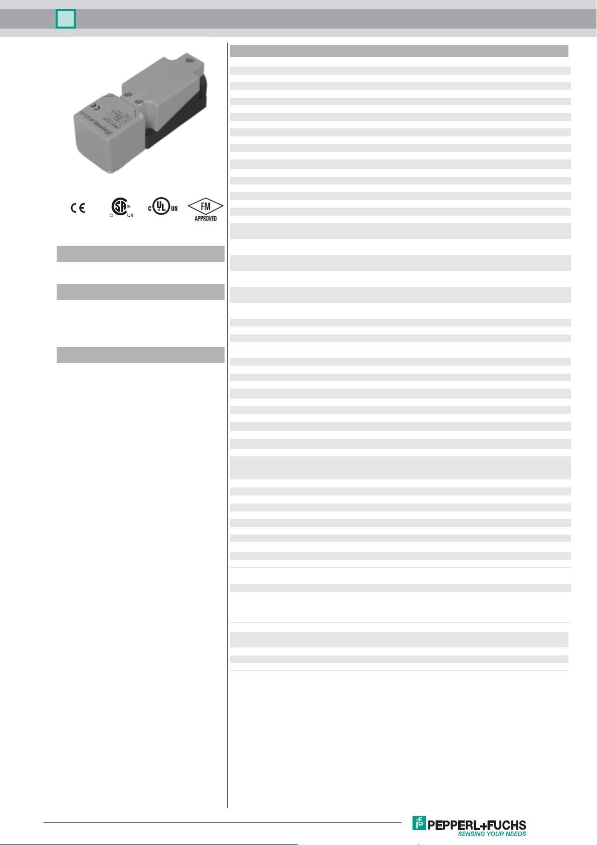
Inductive sensor NBB15-U1K-E2-3G-3D
Technical Data
General specifications
Switching function Normally open (NO)
Output type PNP
Rated operating distance sn15 mm
Installation flush
Output polarity DC
Model Number
NBB15-U1K-E2-3G-3D
Features
• Sensor head bidirectional and
rotatable
• 4 LEDs indicator for 360° visibility
• 15 mm flush
Accessories
MHW 01
Modular mounting bracket
Assured operating distance s
Actual operating distance sr13.5 ... 16.5 mm typ. 15 mm
Reduction factor r
Reduction factor rCu 0.3
Reduction factor r
Reduction factor r
Output type 3-wire
0.33
Al
0.74
304
0.41
Brass
Nominal ratings
Operating voltage UB10 ... 30 V
Switching frequency f 0 ... 200 Hz
Hysteresis H typ. 5 %
Reverse polarity protection reverse polarity protected
Short-circuit protection pulsing
Voltage drop Ud≤ 2 V
Voltage drop at I
Voltage drop IL = 1 mA, switching element
on U
d
Voltage drop I
element on U
Voltage drop IL = 20 mA, switching
element on U
Voltage drop I
element on U
Voltage drop IL = 100 mA, switching
element on U
Voltage drop I
element on U
Design data
Operating current I
Off-state current I
Off-state current T
element off
No-load supply current I
Time delay before availability t
Operating voltage indicator LED, green
Switching state indicator LED, yellow
L
= 10 mA, switching
L
d
d
= 50 mA, switching
L
d
d
= 200 mA, switching
L
d
=40 °C, switching
U
Functional safety related parameters
MTTFd 1242 a
Mission Time (TM) 20 a
Diagnostic Coverage (DC) 0 %
Ambient conditions
Ambient temperature -25 ... 85 °C (-13 ... 185 °F)
Mechanical specifications
Connection type screw terminals
Information for connection A maximum of two conductors with the same core cross section
Core cross-section up to 2.5 mm
Minimum core cross-section
Maximum core cross-section
Housing material PA
Sensing face PA
Degree of protection IP68 / IP69K
Mass 225 g
Note Tightening torque: 1.8 Nm (housing)
General information
Use in the hazardous area see instruction manuals
Category
Compliance with standards and
directives
Standard conformity
Standards
Approvals and certificates
FM approval hazardous (classified) location
UL approval cULus Listed, General Purpose
CSA approval cCSAus Listed, General Purpose
CCC approval CCC approval / marking not required for products rated ≤36 V
0 ... 12.15 mm
a
0.5 ... 2.3 V typ. 0.9 V
0.8 ... 2.2 V typ. 1.4 V
0.9 ... 2.3 V typ. 1.5 V
0.9 ... 2.5 V typ. 1.6 V
1 ... 2.6 V typ. 1.8 V
1.2 ... 2.8 V typ. 2 V
0 ... 200 mA
L
0 ... 0.5 mA typ. 0.01 mA
r
≤ 100 µA
≤ 20 mA
0
80 ms
v
may be mounted on one terminal connection!
tightening torque 1.2 Nm + 10 %
without wire end ferrule 0.5 mm2 , with connector sleeves 0.34 mm
without wire end ferrule 2.5 mm
2
2
, with connector sleeves 1.5 mm
3G; 3D
EN 60947-5-2:2007
EN 60947-5-2/A1:2012
IEC 60947-5-2:2007
IEC 60947-5-2 AMD 1:2012
Non-incendive
2
2
Release date: 2017-11-15 13:02 Date of issue: 2017-11-15 209261_eng.xml
Refer to “General Notes Relating to Pepperl+Fuchs Product Information”.
1
Inductive sensor NBB15-U1K-E2-3G-3D
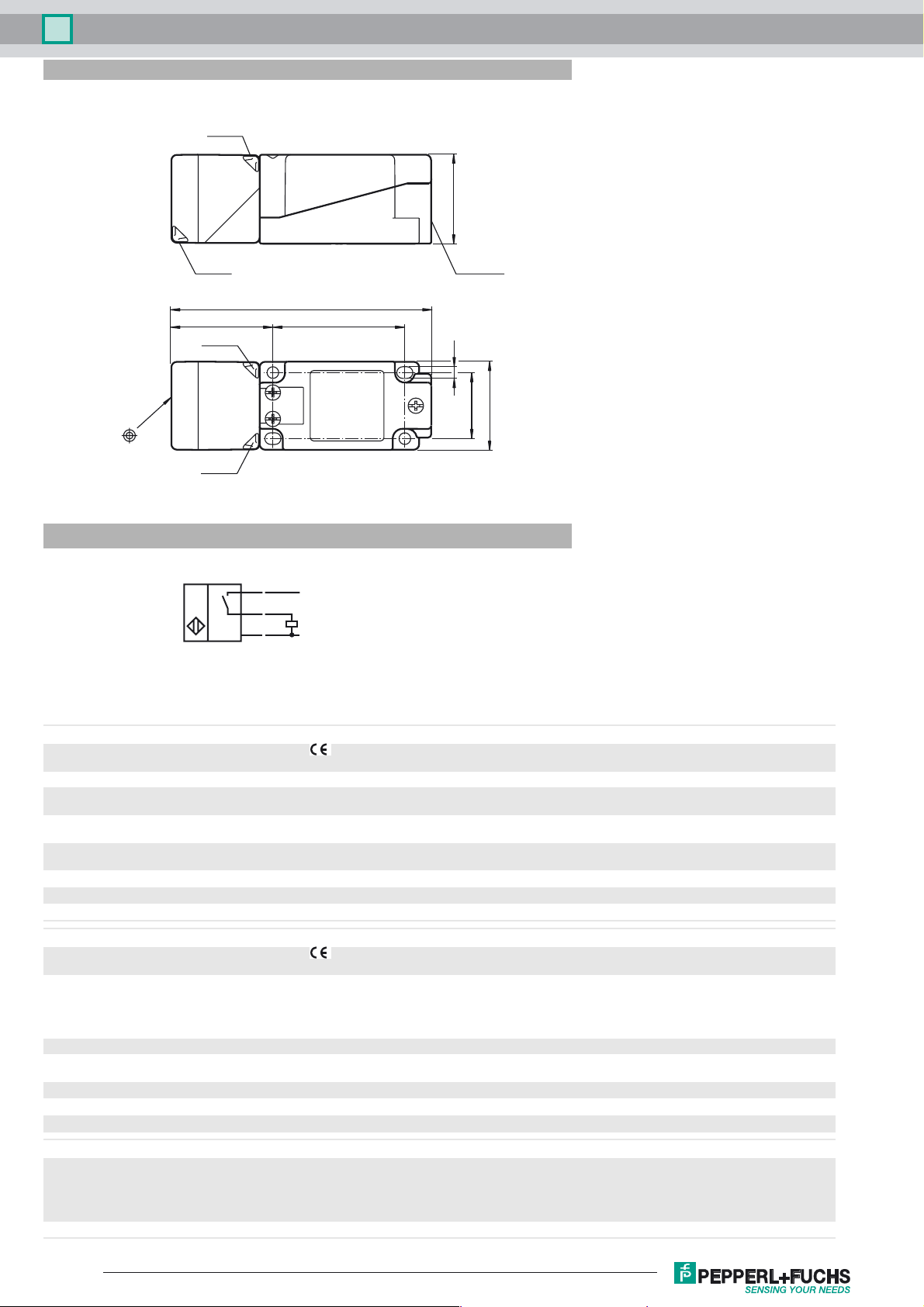
Dimensions
LED ye
40
LED gn
Electrical Connection
LED gn
LED ye
BN
BK
BU
118
M20 x 1.5
6046
5.3
30
40
L+
L-
Equipment protection level Gc (nA)
CE marking
Special conditions
Maximum operating current IL
Maximum operating voltage U
Maximum permissible ambient temperature T
at U
at U
at U
Equipment protection level Dc (tc)
CE marking
General The corresponding datasheets, declarations of conformity, EC-type examination certificates, certifications, and
Special conditions
Maximum permissible ambient temperature T
at U
at U
at U
Equipment protection level Dc (tD)
General The apparatus has to be operated according to the appropriate data in the data sheet and in this instruction manual.
Special conditions
=30 V, IL=200 mA
Bmax
=30 V, IL=100 mA
Bmax
=30 V, IL=50 mA
Bmax
=30 V, IL=200 mA
Bmax
=30 V, IL=100 mA
Bmax
=30 V, IL=50 mA
Bmax
Refer to “General Notes Relating to Pepperl+Fuchs Product Information”.
Bmax
The maximum permissible load current must be restricted to the values given in the following list. High load currents
and load short-circuits are not permitted.
The maximum permissible operating voltage UB max is restricted to the values in the following list. Tolerances are
not permissible.
dependant of the load current IL and the max. operating voltage U
Umax
Information can be taken from the following list.
50 °C (122 °F)
53 °C (127.4 °F)
54 °C (129.2 °F)
control draw see datasheets), form an integral part of this document. These documents can
be found at The maximum surface temperature of the device was determined without a
layer of dust of the information in this instruction manual is more specific than the
information provided in the datasheet.
dependant of the load current I
Umax
Information can be taken from the following list.
50 °C (122 °F)
53 °C (127.4 °F)
54 °C (129.2 °F)
The maximum surface temperature has been determined in accordance with method A without a dust layer on the
equipment.
The data stated in the data sheet are restricted by this operating instruction!
The special conditions must be adhered to!
and the max. operating voltage U
L
Bmax
Bmax
2
Release date: 2017-11-15 13:02 Date of issue: 2017-11-15 209261_eng.xml

Inductive sensor NBB15-U1K-E2-3G-3D
Maximum permissible ambient temperature T
at U
at U
at U
=30 V, IL=200 mA
Bmax
=30 V, IL=100 mA
Bmax
=30 V, IL=50 mA
Bmax
dependant of the load current IL and the max. operating voltage U
Umax
Information can be taken from the following list.
50 °C (122 °F)
53 °C (127.4 °F)
54 °C (129.2 °F)
Bmax
Release date: 2017-11-15 13:02 Date of issue: 2017-11-15 209261_eng.xml
Refer to “General Notes Relating to Pepperl+Fuchs Product Information”.
3
 Loading...