

Inductive sensor NBB10-30GM50-WO-10M
Dimensions
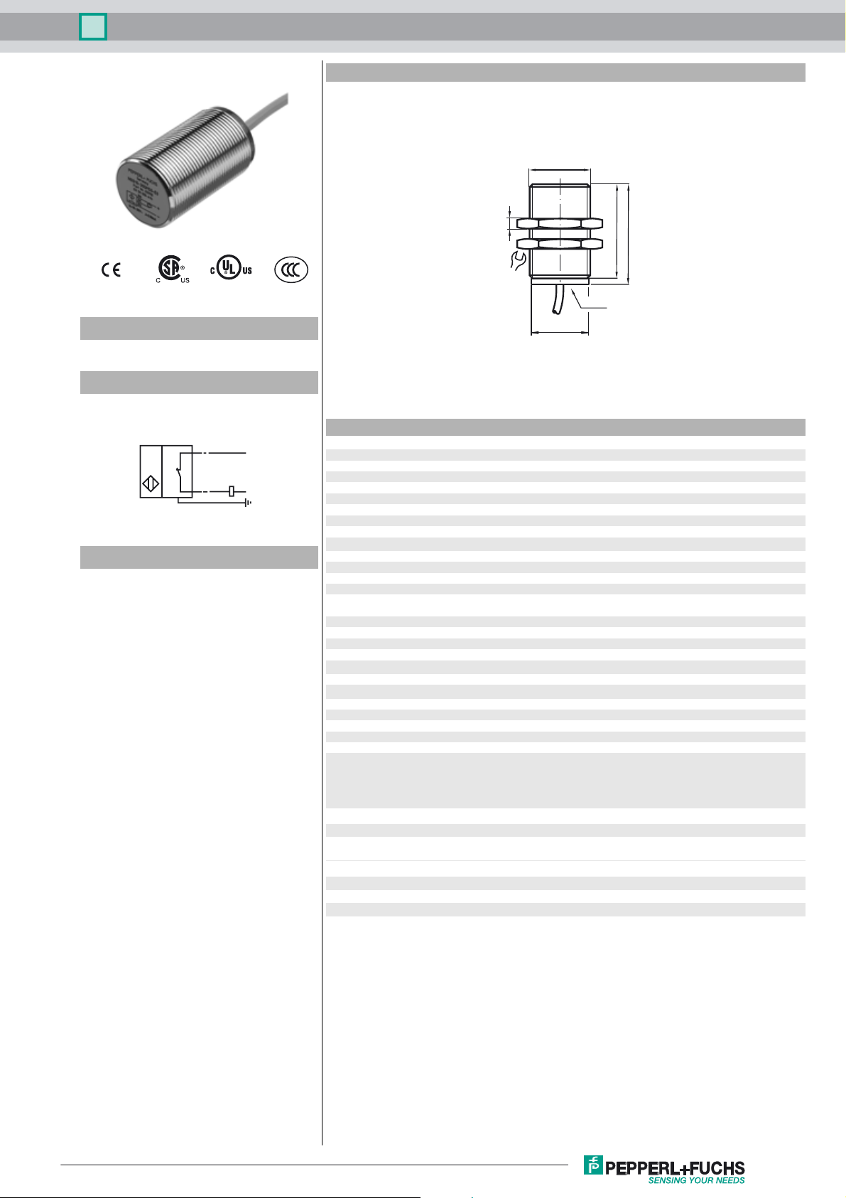
M30 x 1.5
Model Number
NBB10-30GM50-WO-10M
Connection
WÖ
BN
I
BU
GY
Accessories
BF 30
Mounting flange, 30 mm
EXG-30
Quick mounting bracket with dead stop
5
S
36
LED(s)
47
50
ø 28.2
Technical Data
L1
N
General specifications
Switching element function AC NC
Rated operating distance s
Installation embeddable
Output polarity AC
Assured operating distance sa0 ... 8.1 mm
Reduction factor r
Reduction factor rCu 0.28
Reduction factor r
Nominal ratings
Operating voltage UB20 ... 253 V
Switching frequency f 0 ... 20 Hz
Hysteresis H typ. 5 %
Voltage drop Ud< 5 V (IL > 50 mA); < 8 V (IL < 50 mA)
Momentary current
(20 ms, 0.1 Hz)
Operating current I
Off-state current I
Operating voltage display LED, green
Indication of the switching state LED, yellow
Ambient conditions
Ambient temperature -25 ... 70 °C (-13 ... 158 °F)
Mechanical specifications
Connection type cable PVC , 10 m
Core cross-section 0.75 mm
Housing material brass, nickel-plated
Sensing face PBT
Protection degree IP67
Note
Compliance with standards and directives
Standard conformity
Standards
Approvals and certificates
UL approval cULus Listed, General Purpose
CSA approval cCSAus Listed, General Purpose
CCC approval Certified by China Compulsory Certification (CCC)
0.33
Al
0.81
V2A
10 mm
n
0 ... 1600 mA
5 ... 200 mA
L
0 ... 1.7 mA
r
2
1)
In the temperature range below 0 °C, permissible operating vol-
tage U
80...253 V
b
Safety fuse ≤ 0.8 A (quick-blow) according to IEC 60127-2 Sheet 1
Recommendation: after a short circuit, check that the device is
functioning correctly.
EN 60947-5-2:2007
IEC 60947-5-2:2007
Release date: 2010-11-16 11:26 Date of issue: 2010-11-16 199640_ENG.xml
Subject to modifications without notice
Pepperl+Fuchs Group
Copyright Pepperl+Fuchs
1
 Loading...