

Pepperl Fuchs NBB10-30GM50-E2-C-V1 Data Sheet
Inductive sensor NBB10-30GM50-E2-C-V1
Technical Data
General specifications
Switching element function PNP NO
Model Number
NBB10-30GM50-E2-C-V1
Features
• 10 mm flush
•3-wire DC
• Weld Immune
• Slag repellant coatings
Accessories
V1-G-2M-PUR
Female cordset, M12, 4-pin, PUR cable
V1-W-2M-PUR
Female cordset, M12, 4-pin, PUR cable
EXG-30
Quick mounting bracket with dead stop
Rated operating distance s
Installation flush
Output polarity DC
Assured operating distance sa0 ... 8.1 mm
Reduction factor r
Reduction factor rCu 0.2
Reduction factor r
Nominal ratings
Operating voltage UB10 ... 30 V DC
Switching frequency f 0 ... 10 Hz
Hysteresis H typ. 5%
Reverse polarity protection reverse polarity protected
Short-circuit protection pulsing
Vol tag e d rop Ud≤ 3 V
Operating current I
Off-state current I
No-load supply current I
Mag. Field strength, AC fields 100 mT
Mag. Field strength, DC fields 100 mT
Functional safety related parameters
MTTFd 1835 a
Mission Time (TM) 20 a
Diagnostic Coverage (DC) 0 %
Indicators/operating means
Operation indicator 4-way dual LED
Ambient conditions
Ambient temperature -25 ... 70 °C (-13 ... 158 °F)
Mechanical specifications
Connection type Connector M12 x 1 , 4-pin
Core cross-section Housing material Brass, PTFE coated
Sensing face PPS
Protection degree IP67
Compliance with standards and directives
Stan dard conf ormit y
Sta ndar ds
Approvals and certificates
UL approval cULus Listed, General Purpose
CSA approval cCSAus Listed, General Purpose
CCC approval CCC approval / marking not required for products rated ≤36 V
0.3
Al
0.6
304
10 mm
n
0 ... 200 mA
L
0 ... 0.5 mA typ. 0.1 µA at 25 °C
r
≤ 17 mA
0
Green: power
Yellow: output
EN 60947-5-2:2007
IEC 60947-5-2:2007
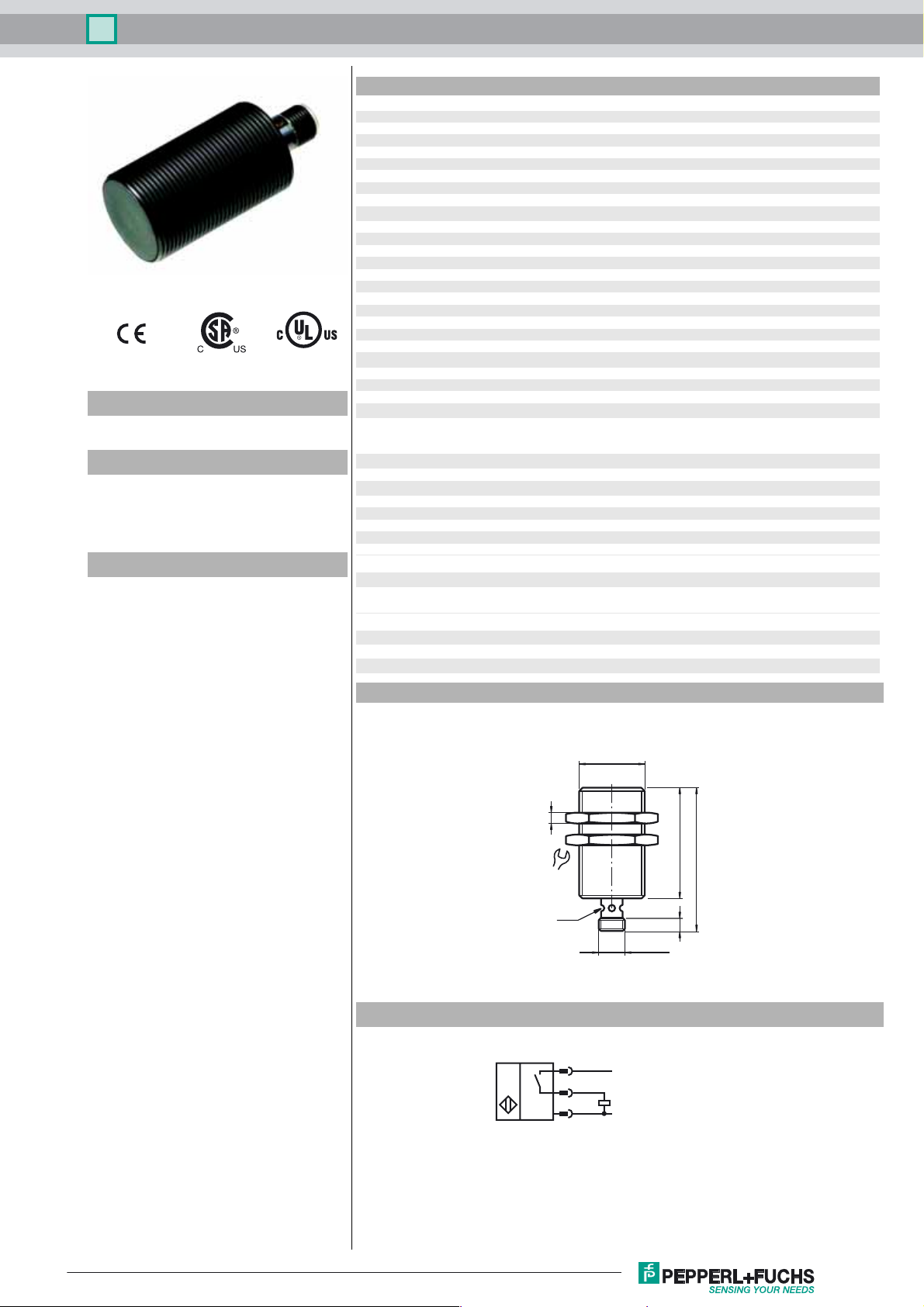
Dimensions
Electrical Connection
M30 x 1.5
5
50
36
LED
M12 x 1
1
4
3
L+
L-
65
6
Release date: 2014-02-12 07:55 Date of issue: 2014-02-12 904406_eng.xml
Refer to “General Notes Relating to Pepperl+Fuchs Product Information”.
1
Inductive sensor NBB10-30GM50-E2-C-V1
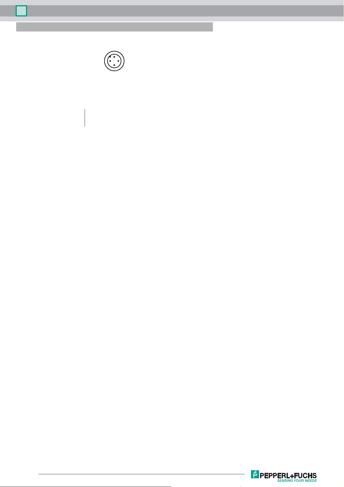
Pinout
1
2
Wire colors in accordance with EN 60947-5-2
1 BN
2 WH
3 BU
4 BK
(brown)
(white)
(blue)
(black)
4
3
Release date: 2014-02-12 07:55 Date of issue: 2014-02-12 904406_eng.xml
Refer to “General Notes Relating to Pepperl+Fuchs Product Information”.
2
 Loading...