

Magnetic field sensor MB-F32-A2-V1
Technical Data
General specifications
Switching element function PNP NO/NC
Model Number
MB-F32-A2-V1
Features
• For mounting on a hydraulic cylinder
• Detects the piston position through the
cylinder wall
• Suitable for magnetic, hydraulic cylinders made of steel
Accessories
V1-G
Female connector, M12, 4-pin, field attachable
V1-W
Female connector, M12, 4-pin, field attachable
V1-W-2M-PUR
Female cordset, M12, 4-pin, PUR cable
V1-G-2M-PUR
Female cordset, M12, 4-pin, PUR cable
Connection Switching output 1 : pin 4
Installation on the cylinder
Output polarity DC
Switching range sbtyp. 50 mm
Nominal ratings
Operating voltage UB10 ... 30 V DC
Reverse polarity protection reverse polarity protected
Short-circuit protection pulsing
Vol tag e d rop U
Operating current I
No-load supply current I
Functional safety related parameters
MTTFd 739 a
Mission Time (TM) 20 a
Diagnostic Coverage (DC) 0 %
Indicators/operating means
LED indicator red: switching state output 1
Ambient conditions
Ambient temperature -25 ... 85 °C (-13 ... 185 °F)
Storage temperature -40 ... 85 °C (-40 ... 185 °F)
Mechanical specifications
Connection type Connector M12 x 1 , 4-pin
Housing material Polyamide (PA)
Sensing face Polyamide (PA)
Degree of protection IP67
Compliance with standards and directives
Stan dard conf ormit y
Sta ndar ds
Approvals and certificates
EAC conformity TR CU 020/2011
CCC approval CCC approval / marking not required for products rated ≤36 V
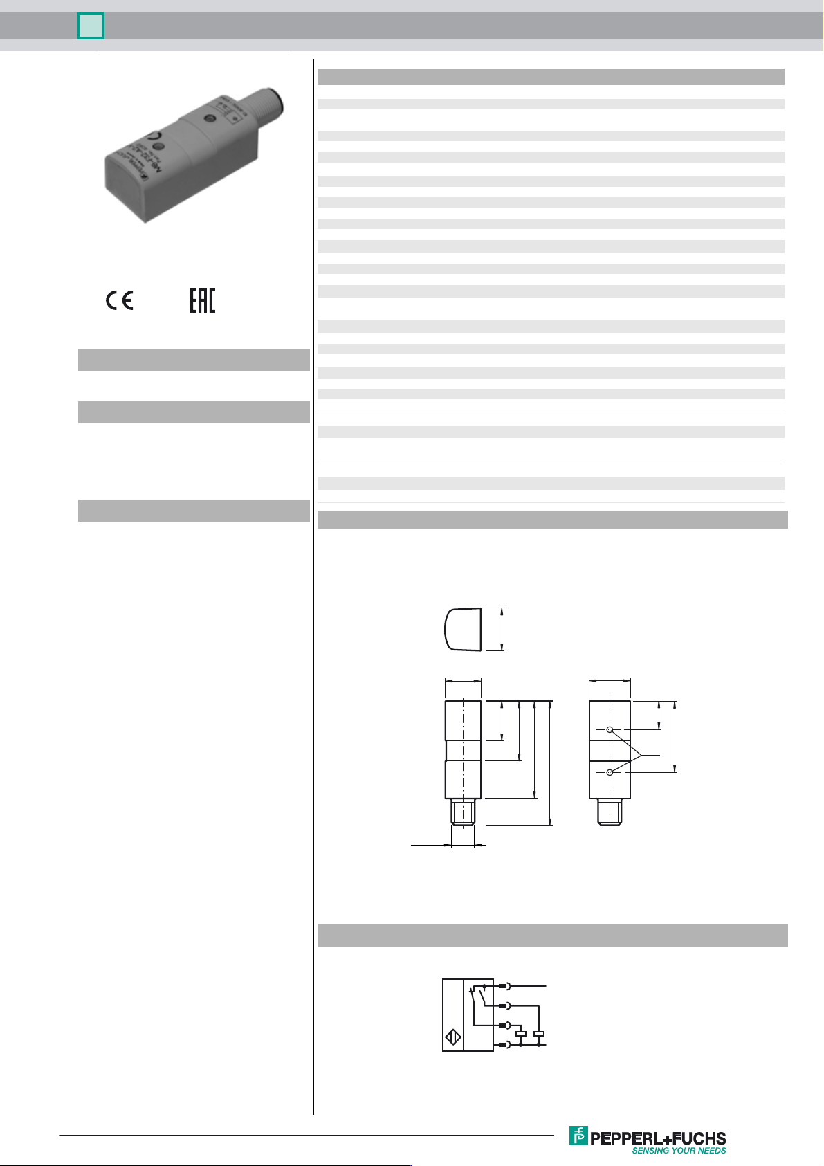
Dimensions
Switching output 2 : pin 2
≤ 1.5 V
d
0 ... 100 mA
L
≤ 30 mA
0
yellow: switching state output 2
EN 60947-5-2:2007
IEC 60947-5-2:2007
2120
M12 x 1
Electrical Connection
18
30
50
64
1
4
2
3
L+
L-
21
14
36
LED
Release date: 2016-06-16 14:30 Date of issue: 2016-06-16 040812_eng.xml
Refer to “General Notes Relating to Pepperl+Fuchs Product Information”.
1
Magnetic field sensor MB-F32-A2-V1
Pinout
1
2
Wire colors in accordance with EN 60947-5-2
1 BN
2 WH
3 BU
4 BK
(brown)
(white)
(blue)
(black)
4
3
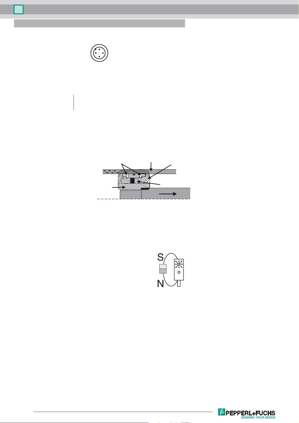
Magnetic System
Primary Construction of the Magnetic System
Non-magnetizable
sealing ring
and sliding ring
package
Non-magnetizable
material
Cylinder wall (steel)
magetically soft
Lines of
magnetic flux
Magnet
For this sensor principle it is not sufficient to simply
mount the permanent magnet onto the piston. A
magnetic system has to be constructed which conducts
the magnetic flux of the permanent magnets directlt into
the cylinder wall in order to achieve the strongest possible
magnetization. For further details regarding the construction
of magnetic systems, refer to the manual. A field trial is
generally recommended before practical operation!
Magnets
The magnets are axially magnetized. It must be
ensured that all magnets are mounted with the same
polarity!
Definition of polarity
An approaching permanent
magnet with the north pole
pointing towards the cable
connection of the sensor causes
output 1 to respond and the red
LED to light.
Antivalient output
By means of the sensor’s antivalent output stage the
appropriate output can be chosen depending on the
polarity of the magnetic system or the mounting location of
the sensor
Mounting
The sensor is mounted directly on the surface towards
the cylinder axis. For this purpose, pressure bands,
tightening straps, or hose band clamps can be used.
Release date: 2016-06-16 14:30 Date of issue: 2016-06-16 040812_eng.xml
Refer to “General Notes Relating to Pepperl+Fuchs Product Information”.
2
 Loading...