

Page 1
BA 240O/98/en/01.10
52027993
185572 01/10 01
Ultrasonic Level Sensor
LUC-M** with HART/4 mA ... 20 mA and
PROFIBUS PA
Description of instrument functions
LUC-M10
LUC-M40
LUC-M20
LUC-M30
Valid as of software version
V 01.04.00 (amplifier)
V 01.04.00 (communication)
Page 2
LUC-M** with HART/4 mA ... 20 mA and PROFIBUS PA
E
+
-
+
E
+
-
F
L
D
E
E
E
-
... ...
KA 183O/98/a2/04.05
52027994
185587 04/05 00
BD
... ...
100%
0%
100 (HART)
2457 (PA)
333 (HART)
33333 (PA)
... ...
... ...
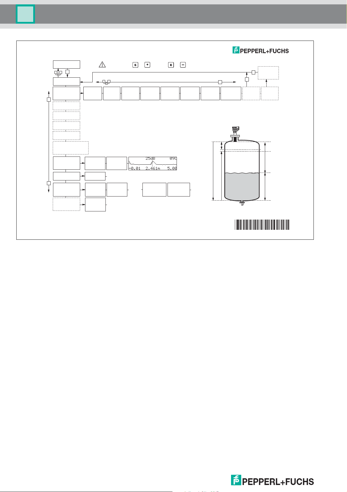
LUC-M** - Quick setup
- dome
ceiling
- horizontal
cyl.
- bypass
...
-
unknown
-
liquid
- > 4 mm
- < 4 mm
- standard
- calm
surface
agitator
- add.
...
input E
(see sketch)
input F
(see sketch)
- ok
- too small
- too big
- unknown
- manual
(see sketch)
000
measured value
group
selection
00
basic setup
01
saf
ety settings
0C
system
parameter
0E
envelope curve
04
linearisation
05
e
xtended calibr.
06
output (HART, FF)
profibus param.(PA)
0A
diagnostics
0A0
present
error
002
tank shape
004
process
cond.
005
empty
calibr.
006
full
calibr.
008
dist./
meas. value
051
check
distance
003
medium
property
052
053
008
dist./
meas. value
0E1
plot settings
0E2
recording
curve
0A1
previous
error
0A4
unlock
parameter
03
temperature
09
display
092
language
BD: blocking distance
0A3
reset
0C0
tag no.
059
blocking
distance
BD is
displayed
(see sketch)
Contrast: + or +
range of
mapping
start
mapping
confirm
or specify
range
suggestion
displayed
D and L are
Short instructions
Short instructions
Contents of the operating instructions
This operating instrucitons contain all functions of the LUC-M** operating menu. All
types of devices and all communication variants (HART and PROFIBUS PA) are considered.
Information on mounting, wiring, trouble shooting and maintenance can be found in the
following documents which are supplied together with the instrument:
• BA 237O/98/en (HART)
• BA 238O/98/en (PROFIBUS PA)
52027994
DOCT-0843A 01/2010 185572
2
Page 3

LUC-M** with HART/4 mA ... 20 mA and PROFIBUS PA
Table of Contents
Short instructions . . . . . . . . . . . . . . . . . . . . . 2
1 Notes on use . . . . . . . . . . . . . . . . . . . . . 5
1.1 Using the table of contents to locate a
function description . . . . . . . . . . . . . . . . . . . . . . . . . 5
1.2 Using the graphic of the function menu to
locate a function description . . . . . . . . . . . . . . . . . . 5
1.3 Using the index of the function menu to
locate a function description . . . . . . . . . . . . . . . . . . 5
1.4 General structure of the operating menu. . . . . . . . . 6
1.5 Display and operating elements . . . . . . . . . . . . . . . 7
1.6 Commissioning . . . . . . . . . . . . . . . . . . . . . . . . . . . 10
2 Function menu LUC-M** . . . . . . . . . . . 11
3 Function group "basic setup" (00). . . 13
3.1 Function "measured value" (000) . . . . . . . . . . . . . 13
3.2 Function "tank shape" (002) . . . . . . . . . . . . . . . . . 13
3.3 Function "medium property" (003). . . . . . . . . . . . . 14
3.4 Function "process cond." (004) . . . . . . . . . . . . . . . 14
3.5 Function "empty calibr." (005) . . . . . . . . . . . . . . . . 16
3.6 Function "blocking dist." (059). . . . . . . . . . . . . . . . 16
3.7 Function "full calibr." (006). . . . . . . . . . . . . . . . . . . 17
3.8 Display (008) . . . . . . . . . . . . . . . . . . . . . . . . . . . . . 17
3.9 Function "check distance" (051) . . . . . . . . . . . . . . 18
3.10 Function "range of mapping" (052) . . . . . . . . . . . . 19
3.11 Funktion "start mapping" (053) . . . . . . . . . . . . . . . 19
3.12 Display (008) . . . . . . . . . . . . . . . . . . . . . . . . . . . . . 20
4 Function group
"safety settings" (01). . . . . . . . . . . . . . 21
4.1 Function "output on alarm" (010). . . . . . . . . . . . . . 21
4.2 Function "output on alarm" (011), HART only . . . . 22
4.3 Function "outp. echo loss" (012) . . . . . . . . . . . . . . 23
4.4 Function "ramp %span/min" (013). . . . . . . . . . . . . 24
4.5 Function "delay time" (014) . . . . . . . . . . . . . . . . . . 24
4.6 Function "safety distance" (015) . . . . . . . . . . . . . . 24
4.7 Function "in safety dist." (016). . . . . . . . . . . . . . . . 25
4.8 Function "ackn. alarm" (017) . . . . . . . . . . . . . . . . . 26
5 Function group "temperature" (03) . . 27
5.1 Function "measured temp." (030) . . . . . . . . . . . . . 27
5.2 Function "max. temp. limit" (031). . . . . . . . . . . . . . 27
5.3 Function "max. meas. temp." (032) . . . . . . . . . . . . 27
5.4 Function "react high temp." (033) . . . . . . . . . . . . . 28
5.5 Function "defect temp. sens." (034) . . . . . . . . . . . 28
6 Function group "linearisation" (04) . . 29
6.1 Function "level/ullage" (040) . . . . . . . . . . . . . . . . . 29
6.2 Function "linearisation" (041). . . . . . . . . . . . . . . . . 30
6.3 Function "customer unit" (042) . . . . . . . . . . . . . . . 33
6.4 Function "table no." (043) . . . . . . . . . . . . . . . . . . . 34
6.5 Function "input level" (044) . . . . . . . . . . . . . . . . . . 34
6.6 Function "input volume" (045) . . . . . . . . . . . . . . . . 35
6.7 Function "max. scale" (046). . . . . . . . . . . . . . . . . . 35
6.8 Function "diameter vessel" (047). . . . . . . . . . . . . . 35
7 Function group
"extended calibr." (05). . . . . . . . . . . . . 36
7.1 Function "selection" (050). . . . . . . . . . . . . . . . . . . . 36
7.2 Function "check distance" (051). . . . . . . . . . . . . . . 36
7.3 Function "range of mapping" (052). . . . . . . . . . . . . 37
7.4 Function "start mapping" (053). . . . . . . . . . . . . . . . 37
7.5 Function "pres. map dist." (054) . . . . . . . . . . . . . . . 38
7.6 Function "cust. tank map" (055) . . . . . . . . . . . . . . . 38
7.7 Function "echo quality" (056) . . . . . . . . . . . . . . . . . 39
7.8 Function "offset" (057) . . . . . . . . . . . . . . . . . . . . . . 39
7.9 Function "output damping" (058) . . . . . . . . . . . . . . 39
7.10 Function "blocking dist." (059) . . . . . . . . . . . . . . . . 40
8 Function group "output" (06) and
"profibus param." (06) . . . . . . . . . . . . . 41
8.1 Function "commun. address" (060), HART only. . . 41
8.2 Function "instrument addr." (060),
PROFIBUS PA only . . . . . . . . . . . . . . . . . . . . . . . . 41
8.3 Function "no. of preambels" (061), HART only. . . . 41
8.4 Function "ident number" (061),
PROFIBUS PA only . . . . . . . . . . . . . . . . . . . . . . . . 42
8.5 Function "thres. main val." (062), HART only. . . . . 42
8.6 Function "set unit to bus" (062),
PROFIBUS PA only . . . . . . . . . . . . . . . . . . . . . . . . 43
8.7 Function "curr. output mode" (063),
HART only . . . . . . . . . . . . . . . . . . . . . . . . . . . . . . . 43
8.8 Function "out value" (063),
PROFIBUS PA only . . . . . . . . . . . . . . . . . . . . . . . . 44
8.9 Function "fixed cur. value" (064), HART only . . . . . 44
8.10 Function "out status" (064),
PROFIBUS PA only . . . . . . . . . . . . . . . . . . . . . . . . 44
8.11 Function "simulation" (065). . . . . . . . . . . . . . . . . . . 45
8.12 Function "simulation value" (066). . . . . . . . . . . . . . 46
8.13 Function "output current" (067), HART only . . . . . . 46
8.14 Function "2nd cyclic value" (067),
PROFIBUS PA only . . . . . . . . . . . . . . . . . . . . . . . . 46
8.15 Function "4mA value" (068), HART only . . . . . . . . 46
8.16 Function "select v0h0" (068),
PROFIBUS PA only . . . . . . . . . . . . . . . . . . . . . . . . 47
8.17 Function "20mA value" (069), HART only . . . . . . . 47
8.18 Function "display value" (069),
PROFIBUS PA only . . . . . . . . . . . . . . . . . . . . . . . . 47
9 Function group
"envelope curve" (0E) . . . . . . . . . . . . . 48
9.1 Function "plot settings" (0E1) . . . . . . . . . . . . . . . . . 48
9.2 Function "recording curve" (0E2) . . . . . . . . . . . . . . 48
9.3 Function "envelope curve display" (0E3) . . . . . . . . 49
10 Function group "display" (09) . . . . . . 51
10.1 Function "language" (092) . . . . . . . . . . . . . . . . . . . 51
10.2 Function "back to home" (093) . . . . . . . . . . . . . . . . 51
10.3 Function "format display" (094) . . . . . . . . . . . . . . . 52
10.4 Function "no.of decimals" (095) . . . . . . . . . . . . . . . 52
10.5 Function "sep. character" (096) . . . . . . . . . . . . . . . 52
10.6 Function "display test" (097). . . . . . . . . . . . . . . . . . 52
DOCT-0843A 01/2010 185572
3
Page 4

LUC-M** with HART/4 mA ... 20 mA and PROFIBUS PA
Table of Contents
11 Function group "diagnostics" (0A) . . . 53
11.1 Function "present error" (0A0) . . . . . . . . . . . . . . . 53
11.2 Function "previous error" (0A1) . . . . . . . . . . . . . . 53
11.3 Function "clear last error" (0A2) . . . . . . . . . . . . . . 53
11.4 Function "reset" (0A3). . . . . . . . . . . . . . . . . . . . . . 54
11.5 Function "unlock parameter" (0A4). . . . . . . . . . . . 55
11.6 Function "measured dist." (0A5) . . . . . . . . . . . . . . 56
11.7 Function "measured level" (0A6) . . . . . . . . . . . . . 57
11.8 Function "detection window" (0A7) . . . . . . . . . . . . 57
11.9 Function "application par." (0A8) . . . . . . . . . . . . . 58
12 Function group
"system parameters" (0C) . . . . . . . . . . 59
12.1 Function "tag no." (0C0) . . . . . . . . . . . . . . . . . . . . 59
12.2 Function "Profile Version" (0C1),
PROFIBUS PA only . . . . . . . . . . . . . . . . . . . . . . . 59
12.3 Function "protocol+sw-no." (0C2). . . . . . . . . . . . . 59
12.4 Function "serial no." (0C4) . . . . . . . . . . . . . . . . . . 60
12.5 Function "distance unit" (0C5) . . . . . . . . . . . . . . . 60
12.6 Function "temperature unit" (0C6) . . . . . . . . . . . . 61
12.7 Function "download mode" (0C8) . . . . . . . . . . . . . 61
13 Function group "service" (0D). . . . . . . 61
14 Signal evaluation. . . . . . . . . . . . . . . . . . 62
14.1 Envelope curve . . . . . . . . . . . . . . . . . . . . . . . . . . . 62
14.2 Interference echo suppression (tank mapping) . . . 63
14.3 Floating Average Curve (FAC) . . . . . . . . . . . . . . . 64
15 Trouble shooting. . . . . . . . . . . . . . . . . . 65
15.1 System error messages. . . . . . . . . . . . . . . . . . . . . 65
15.2 Application errors. . . . . . . . . . . . . . . . . . . . . . . . . . 67
Index function menu . . . . . . . . . . . . . . . . . . 73
DOCT-0843A 01/2010 185572
4
Page 5

LUC-M** with HART/4 mA ... 20 mA and PROFIBUS PA
Notes on use
1 Notes on use
You have various options for accessing the descriptions of instrument functions or how
to enter parameters.
1.1 Using the table of contents to locate a function description
All the functions are listed in the table of contents sorted by function group (e. g.
"basic setup", "safety settings", etc.). You can access a more detailed description of a
function by using a page reference.
The table of contents is on page 3.
1.2 Using the graphic of the function menu to locate a function description
This guides you step by step from the highest level, the function groups, to the exact
function description you require.
All the available function groups and instrument functions are listed in the table
(see page 11). Select your required function group or function. You can access an exact
description of the function group or function by using a page reference.
1.3 Using the index of the function menu to locate a function description
To simplify navigation within the function menu, each function has a position which is
shown in the display. You can access each function via a page reference in the function
menu index (see page 73) which lists all the function names alphabetically and
numerically.
DOCT-0843A 01/2010 185572
5
Page 6
LUC-M** with HART/4 mA ... 20 mA and PROFIBUS PA
Notes on use
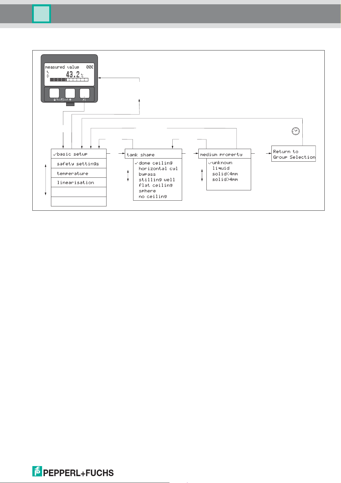
1.4 General structure of the operating menu
The operating menu is made up of two levels:
• Function groups (00, 01, 03, …, 0C, 0E):
The individual operating Selection of the instrument are split up roughly into different
function groups. The function groups that are available include, e. g.: "basic
setup", "safety settings", "output", "display", etc.
• Functions (001, 002, 003, …, 0E2, 0E3):
Each function group consists of one or more functions. The functions perform the
actual operation or parameterisation of the instrument. Numerical values can be
entered here and parameters can be selected and saved. The available functions
of the "basic setup" (00) function group include, e. g.: "tank shape" (002),
"medium property" (003), "process cond." (004), "empty calibr." (005), etc.
If, for example, the application of the instrument is to be changed, carry out the following
procedure:
1. Select the "basic setup" (00) function group.
2. Select the "tank shape" (002) function (where the existing tank shape is selected).
1.4.1 Identifying the functions
For simple orientation within the function menus (see page 11 ff.), for each function a
position is shown on the display.
function group
The first two digits identify the function group:
• basic setup 00
• safety settings 01
• temperature 03
…
The third digit numbers the individual functions within the function group:
• basic setup 00 • tank shape 002
• medium property 003
• process cond. 004
…
Hereafter the position is always given in brackets (e. g. "tank shape" (002)) after the
described function.
function
DOCT-0843A 01/2010 185572
6
Page 7
LUC-M** with HART/4 mA ... 20 mA and PROFIBUS PA
Bargraph
Selection list
Help texts
Envelope
curve
Label
Label
Position in menu
Position in menu
Value
Unit
Symbol
Measured value
display
Group selection
Function with
free parameter
Envelope curve
display
Notes on use
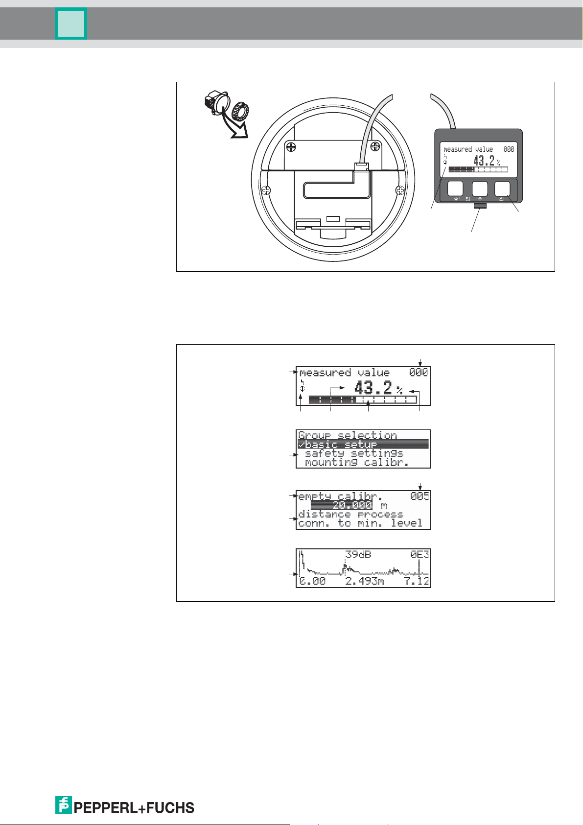
1.5 Display and operating elements
ENDRES
MI
Ord
CR
S+H
e
r
Co
O
S
A
d
er
PI
e
.
:
-No
USE
L
O
.:
T
R
I
I
Messberei
Measur
c
h
ing
r
a
nge
U 16...
m
ax.
4..
3
2
6
0
.2
V DC
m
0 m
A
IP
6
5
T
>
A
7
0
C
:
t
>85
C
Made in Germany Maulburg
LCD
(Liquid crystal display)
–
+
E
Symbols
Snap-fit
1.5.1 Display
Liquid crystal display (LCD):
Four lines with 20 characters each. Display contrast adjustable through key
combination.
3 keys
DOCT-0843A 01/2010 185572
7
Page 8
LUC-M** with HART/4 mA ... 20 mA and PROFIBUS PA
Notes on use
1.5.2 Display symbols
The following table describes the symbols that appear on the liquid crystal display:
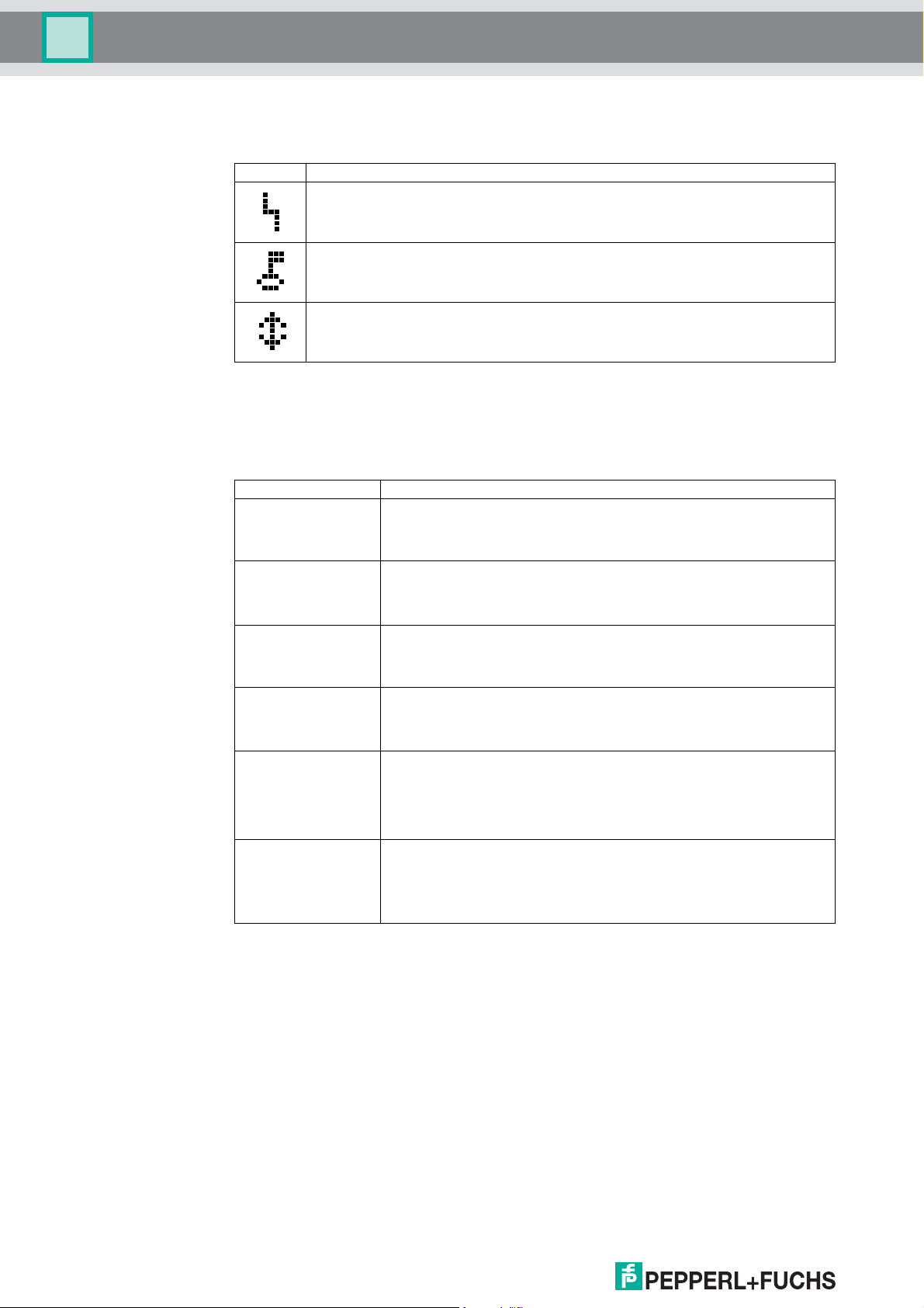
Symbol Meaning
ALARM_SYMBOL
This alarm symbol appears when the instrument is in an alarm state. If the symbol flashes, this
indicates a warning.
LOCK_SYMBOL
This lock symbol appears when the instrument is locked, i. e. if no input is possible.
COM_SYMBOL
This communication symbol appears when a data transmission via e. g. HART or
PROFIBUS PA is in progress.
1.5.3 Key assignment
The operating elements are located inside the housing and are accessible for operation
by opening the lid of the housing.
Function of the keys
Key(s) Meaning
O
S
X
and
O
and
S
and S and
O
or
V
or W
or
Z
F
F
or
F
Navigate upwards in the selection list
Edit numeric value within a function
Navigate downwards in the selection list
Edit numeric value within a function
Navigate to the left within a function group
Navigate to the right within a function group, confirmation
Contrast settings of the LCD
Hardware lock/unlock
After a hardware lock, an operation of the instrument via display or
communication is not possible!
F
The hardware can only be unlocked via the display. An unlock parameter must be
entered to do so.
DOCT-0843A 01/2010 185572
8
Page 9
LUC-M** with HART/4 mA ... 20 mA and PROFIBUS PA
E
+
–
X
X
X
X
S
SS
O
OO
FF
>3 s
F
...
2x
...
...
Notes on use
1.5.4 Operation using the on-site display LUC-Z15
1. Change from Measured Value Display to Group Selection by pressing F.
2. Press S or O to select the required Function Group and confirm by pressing F.
The active selection is marked by a in front of the menu text.
3. Activate Edit mode with O or S .
Selection menus
a) Select the required Parameter in selected function with S or O .
b) F confirms selection → appears in front of the selected parameter.
c) F confirms the edited value → system quits edit mode.
d) O and S (= Q) interrupts selection → system quits edit mode.
Typing in numerals and text
a) Press O or S to edit the first character of the numeral/text.
b) F positions the cursor at the next character → continue with a) until you have
completed your input.
c) If a ↵ symbol appears at the cursor, press F to accept the value entered →
system quits edit mode.
d) If a ← symbol appears at the cursor, press F to return to the previous character
(e. g. for correction of entries).
e) O and S (= Q)
4. Press F to select the next function.
5. Press O and S (= Q) once → return to previous function.
Press O and S (= Q) twice → return to Group Selection.
6. Press O and S (= Q) to return to Measured value display.
interrupts selection; → system quits edit mode.
DOCT-0843A 01/2010 185572
9
Page 10
LUC-M** with HART/4 mA ... 20 mA and PROFIBUS PA
Notes on use
1.6 Commissioning
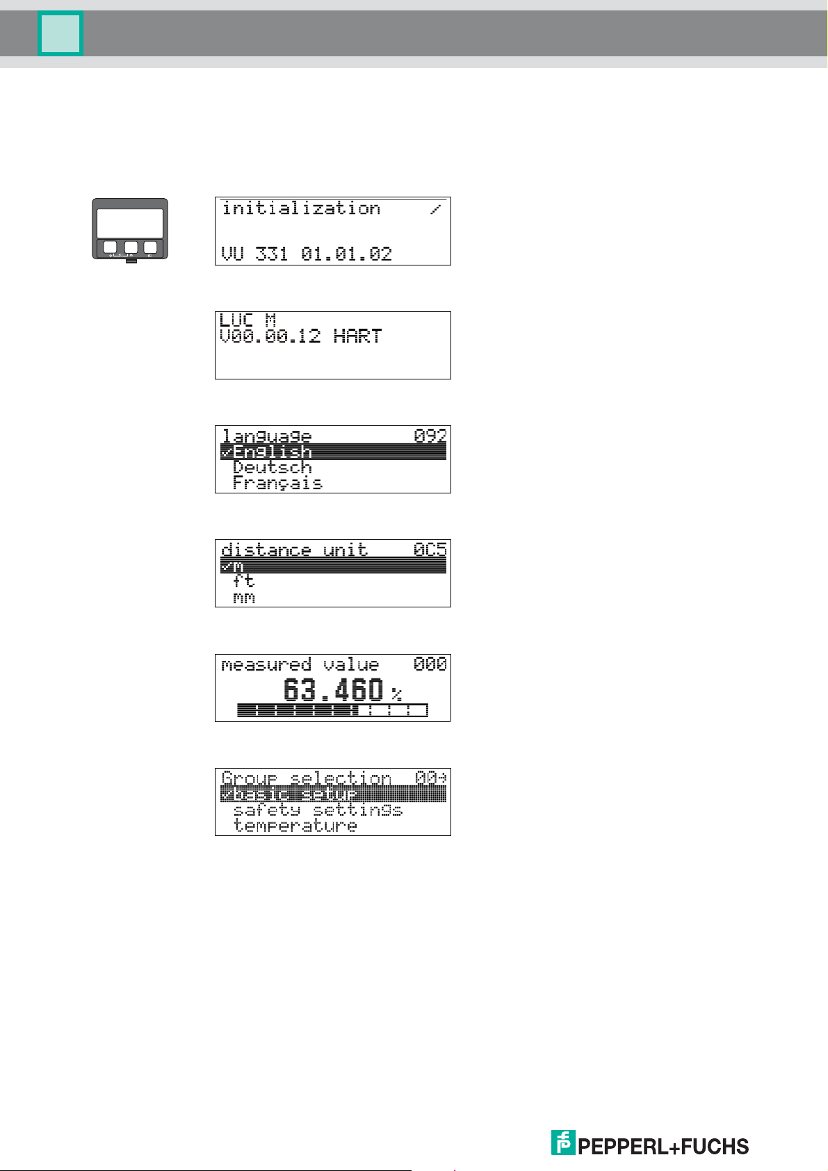
1.6.1 Switching on the measuring device
When the instrument is switched on for the first time, the following messages appear on
the display:
–
+
E
After 5 s, the following message appears
After 5 s or after you have pressed F the
following message appears
Select the language
(this message appears the first time the
instrument is switched on)
Select the basic unit
(this message appears the first time the
instrument is switched on)
The current measured value is displayed
After F is pressed, you reach the group
selection.
This selection enables you to perform the basic
setup
10
DOCT-0843A 01/2010 185572
Page 11

LUC-M** with HART/4 mA ... 20 mA and PROFIBUS PA
Function menu LUC-M**
2 Function menu LUC-M**
Function group Function Description
basic setup 00
(see page 13)
measured value 000
tank shape 002
medium property 003
process cond. 004
empty calibr. 005
blocking dist. 059
full calibr. 006
display 008
check distance 051
range of mapping 052
start mapping 053
display 008
page 13
page 13
page 14
page 14
page 16
page 16
page 17
page 17
page 18
page 19
page 19
page 20
safety settings 01
(see page 21)
temperature 03
(see page 27)
linearisation 04
(see page 29)
output on alarm 010
output on alarm (HART only) 011
outp. echo loss 012
ramp %span/min 013
delay time 014
safety distance 015
in safety dist. 016
ackn. alarm 017
measured temp. 030
max. temp. limit 031
max. meas. temp. 032
react high temp. 033
defect temp. sens. 034
level/ullage 040
linearisation 041
customer unit 042
table no. 043
input level 044
input volume 045
max. scale 046
diameter vessel 047
page 21
page 22
page 23
page 24
page 24
page 24
page 25
page 26
page 27
page 27
page 27
page 28
page 28
page 29
page 30
page 33
page 34
page 34
page 35
page 35
page 35
extended calibr. 05
(see page 36)
DOCT-0843A 01/2010 185572
selection 050
check distance 051
range of mapping 052
start mapping 053
pres. map dist. 054
cust. tank map 055
echo quality 056
offset 057
output damping 058
blocking dist. 059
page 36
page 36
page 37
page 37
page 38
page 38
page 39
page 39
page 39
page 40
11
Page 12
LUC-M** with HART/4 mA ... 20 mA and PROFIBUS PA
Function menu LUC-M**
Function group Function Description
output 06
profibus param. 06
PROFIBUS PA only
(see page 41)
commun. address (HART only) 060
instrument addr. (PROFIBUS PA only) 060
no. of preambels (HART only) 061
ident number (PROFIBUS PA only) 061
thres. main val. (HART only) 062
set unit to bus (PROFIBUS PA only) 062
current output mode (HART only) 063
out value (PROFIBUS PA only) 063
fixed cur. value (HART only) 064
out status (PROFIBUS PA only) 064
simulation 065
simulation value 066
output current (HART only) 067
2nd cyclic value (PROFIBUS PA only) 067
4mA value (HART only) 068
select v0h0 (PROFIBUS PA only) 068
20mA value (HART only) 069
display value (PROFIBUS PA only) 069
page 41
page 41
page 41
page 42
page 42
page 43
page 43
page 44
page 44
page 44
page 45
page 46
page 46
page 46
page 46
page 47
page 47
page 47
envelope curve 0E
(see page 48)
display 09
(see page 51)
diagnostics 0A
(see page 53)
system parameter 0C
(see page 59)
plot settings 0E1
recording curve 0E2
envelope curve display 0E3
language 092
back to home 093
format display 094
no.of decimals 095
sep. character 096
display test 097
present error 0A0
previous error 0A1
clear last error 0A2
reset 0A3
unlock parameter 0A4
measured dist. 0A5
measured level 0A6
detection window 0A7
application par. 0A8
tag no. 0C0
Profile Version (PROFIBUS PA only) 0C1
protocol+sw-no. 0C2
serial no. 0C4
distance unit 0C5
temperature unit 0C6
download mode 0C8
page 48
page 48
page 49
page 51
page 51
page 52
page 52
page 52
page 52
page 53
page 53
page 53
page 54
page 55
page 56
page 57
page 57
page 58
page 59
page 59
page 59
page 60
page 60
page 61
page 61
12
service 0D
page 61
DOCT-0843A 01/2010 185572
Page 13
LUC-M** with HART/4 mA ... 20 mA and PROFIBUS PA
E
+
–
E
+
–
E
+
–
Function group "basic setup" (00)
3 Function group "basic setup" (00)
3.1 Function "measured value" (000)
This function displays the current measured value in the selected unit (see "customer
unit" (042) function). The number of places after decimal point can be selected in the
"no.of decimals" (095) function.
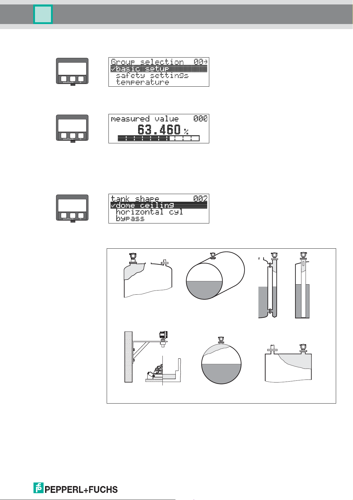
3.2 Function "tank shape" (002)
This function is used to select the tank shape.
Selection:
dome ceiling
horizontal cyl.
bypass stilling well
(ultrasonic guide pipe)
no ceiling
e. g. dumps, open levels
chanels, weirs
DOCT-0843A 01/2010 185572
sphere
flat ceiling
13
Page 14
LUC-M** with HART/4 mA ... 20 mA and PROFIBUS PA
Function group "basic setup" (00)
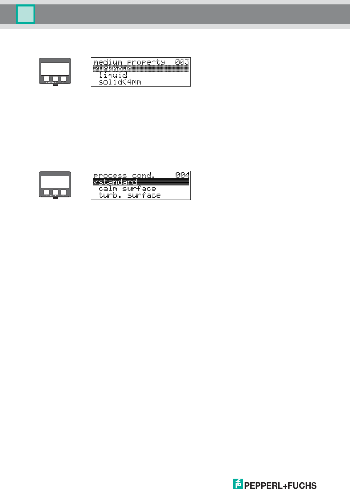
3.3 Function "medium property" (003)
–
+
E
This function is used to set the medium properties:
Selection:
• unknown (e. g. pasty media such as greases, creams, gels etc.)
•liquid
• solid, grain size < 4mm (fine)
• solid, grain size > 4mm (coarse)
3.4 Function "process cond." (004)
–
+
E
For this function, you have the following options:
14
DOCT-0843A 01/2010 185572
Page 15
LUC-M** with HART/4 mA ... 20 mA and PROFIBUS PA
Function group "basic setup" (00)
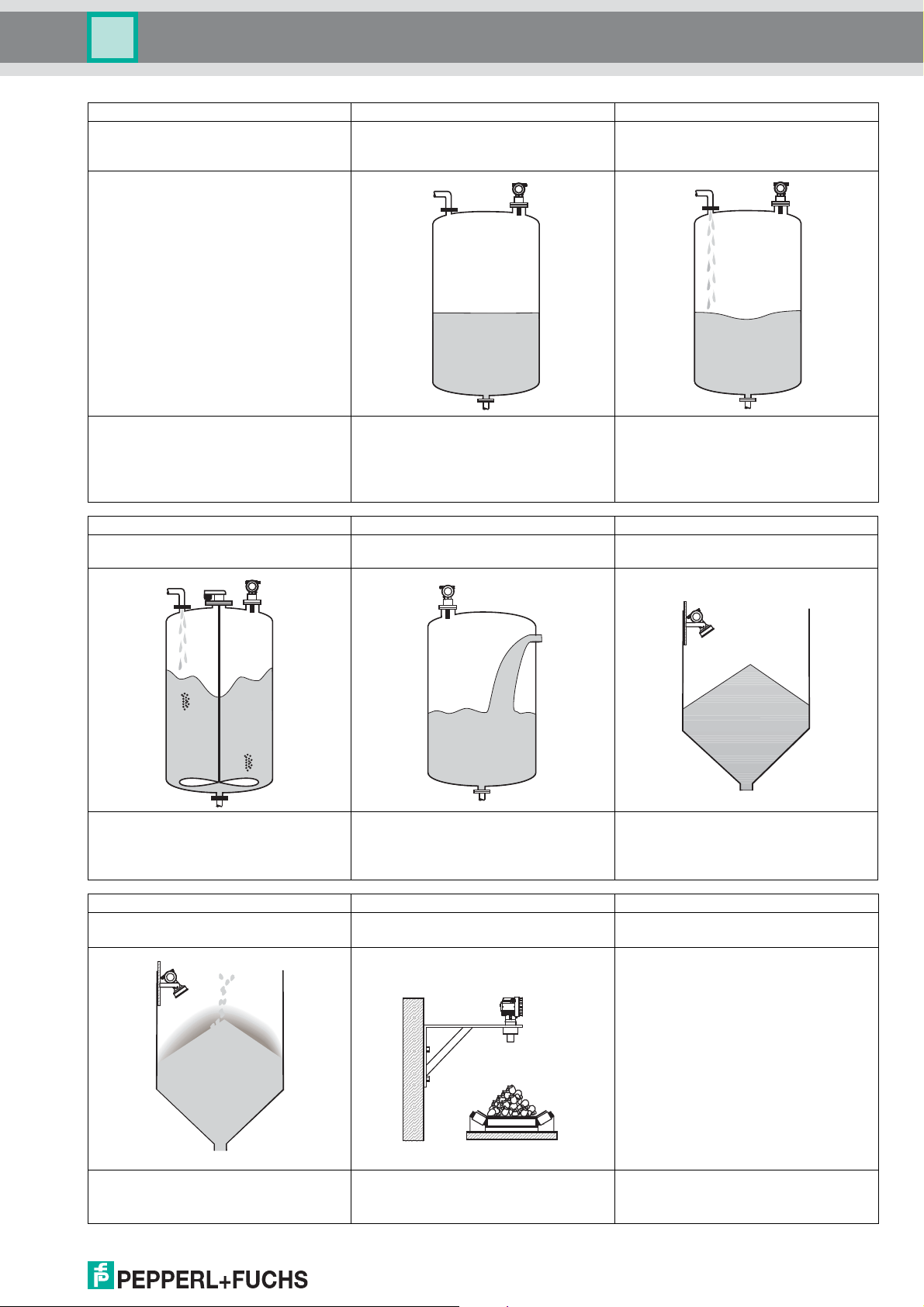
Standard liquids Calm surface Turb. surface
For all fluid applications which do not fit in any
of the following groups.
Storage tanks with immersion tube or bottom
filling
Storage/accumulation tanks with uneven
surface due to free filling, mixing nozzles or
small bottom stirrers.
The filters and output damping are set to
average values.
Add. agitator Fast change Standard solid
Moving surfaces (poss. with vortex formation)
due to agitators
Special filters for stabilising the input signal
are set to large values.
- stable measured value
- medium reaction time
The averaging filters and output damping are
set to large values.
- stable measured value
- accurate measurement
- slow reaction time
Rapid level change, particularly in small tanks For all bulk solids applications which do not fit
The averaging filters are set to small values.
- rapid reaction time
- possibly unstable measured value
Special filters for stabilising the input signal
are activated.
- stable measured value
- medium reaction time
in any of the following groups.
The filter and output damping are set to
average values.
Solid dusty Conveyor belt Test:no filter
Dusty bulk solids Bulk solids with rapid level change All the filters can be switched off for purposes
The filters are set to detect even relatively
weak signals.
DOCT-0843A 01/2010 185572
The averaging filters are set to small values.
- rapid reaction time
- possibly unstable measured value
of service and diagnosis.
All filters off
15
Page 16
LUC-M** with HART/4 mA ... 20 mA and PROFIBUS PA
Function group "basic setup" (00)
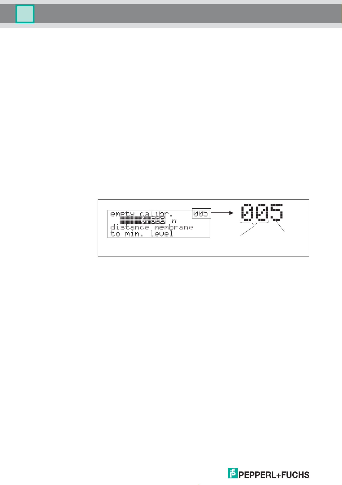
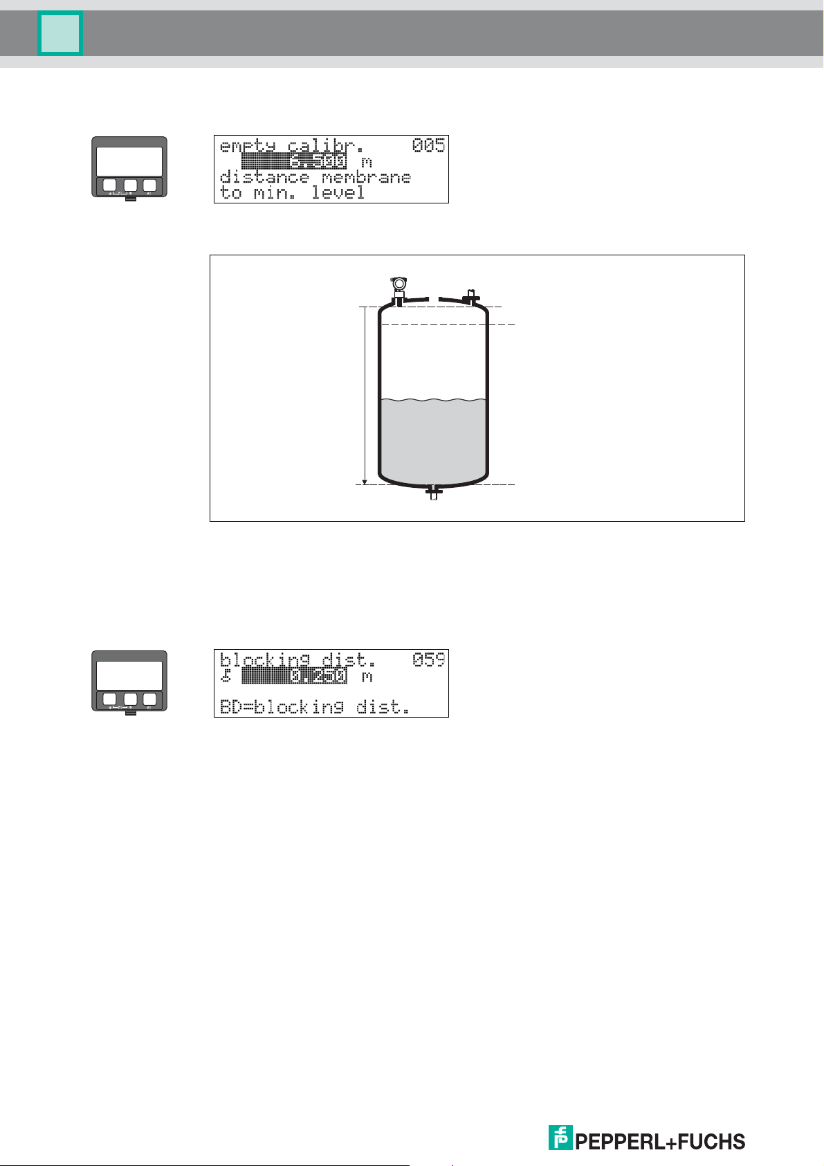
3.5 Function "empty calibr." (005)
–
+
E
This function is used to enter the distance from the sensor membrane (reference point
of the measurement) to the minimum level (= zero).
100 %
Empty calibration
E
Caution!
"
For dish bottoms or conical outlets, the zero point should be no lower than the point at
which the radar beam hits the bottom of the tank.
E:
0 %
3.6 Function "blocking dist." (059)
–
+
E
In this function the blocking distance is displayed. Level echoes within the blocking
distance can not be detected by the LUC-M**. Make sure that the maximum level will
never run into the blocking distance.
16
DOCT-0843A 01/2010 185572
Page 17
LUC-M** with HART/4 mA ... 20 mA and PROFIBUS PA
E
+
–
Full calibration (span)
Blocking distance
Safety distance
100 %
0 %
F
BD
SD
F:
BD:
SD:
E
+
–
Function group "basic setup" (00)
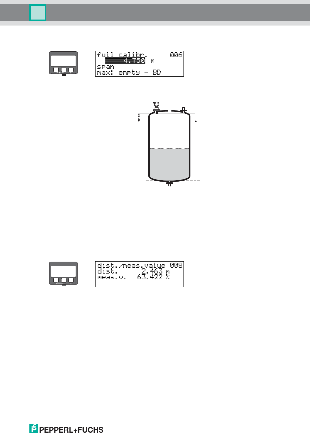
3.7 Function "full calibr." (006)
This function is used to enter the distance from the minimum level to the maximum level
(= span).
Caution!
"
The maximum level may not project into the blocking distance (BD). If the blocking
distance is compromised, it may cause device malfunction.
After basic calibration, enter a safety distance (SD) in the "safety distance" (015)
function. If the level is within this safety distance, the LUC-M** signals a warning or an
alarm, depending on your selection in the "in safety distance" (016) function.
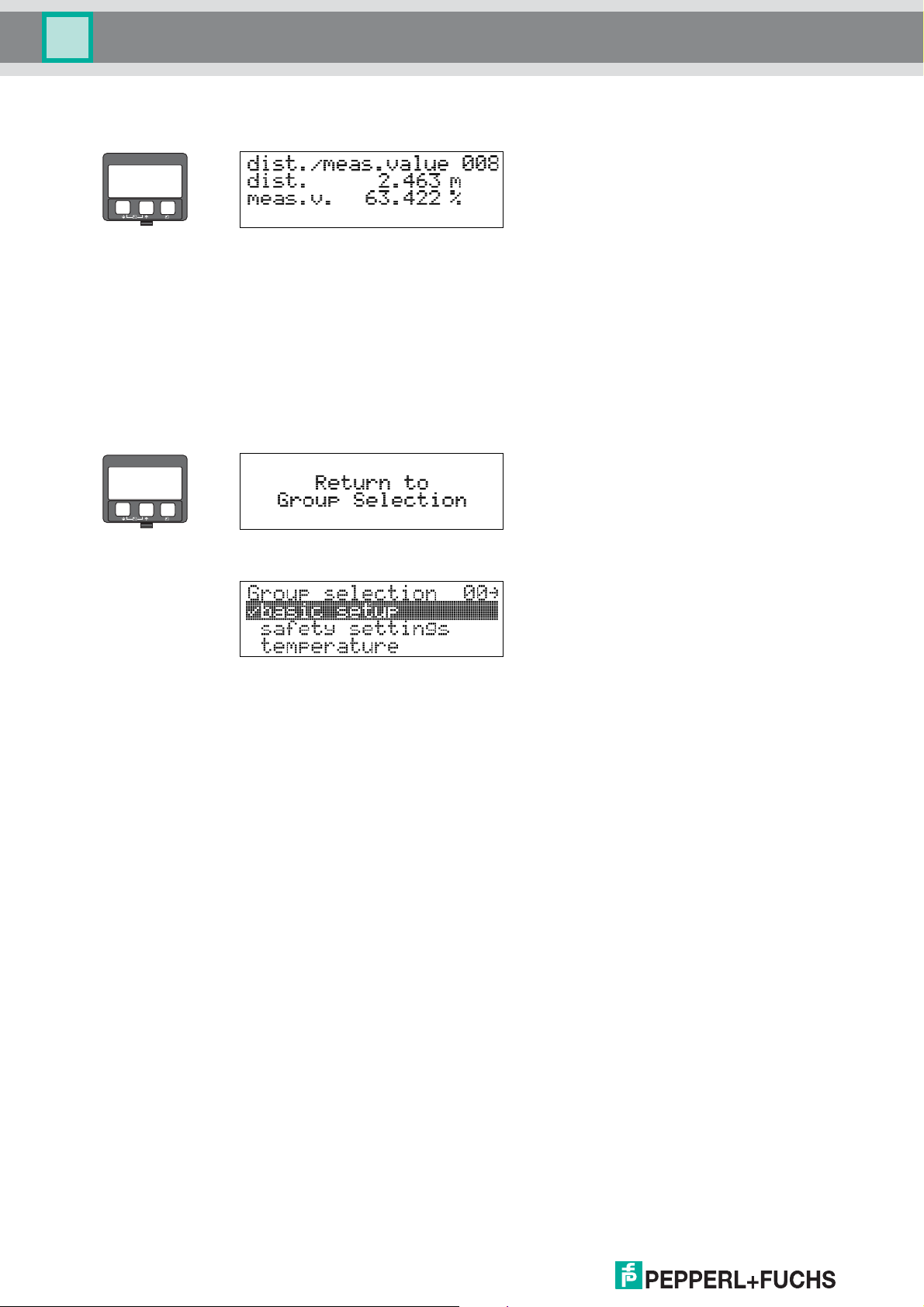
3.8 Display (008)
The distance measured from the sensor membrane to the product surface and the
level calculated with the aid of the empty calibration are displayed. Check whether the
values correspond to the actual level or the actual distance. The following cases can
occur:
• Distance correct – level correct continue with the next function,
"check distance" (051).
• Distance correct – level incorrect check "empty calibr." (005).
• Distance incorrect – level incorrect continue with the next function,
"check distance" (051).
DOCT-0843A 01/2010 185572
17
Page 18
LUC-M** with HART/4 mA ... 20 mA and PROFIBUS PA
Function group "basic setup" (00)
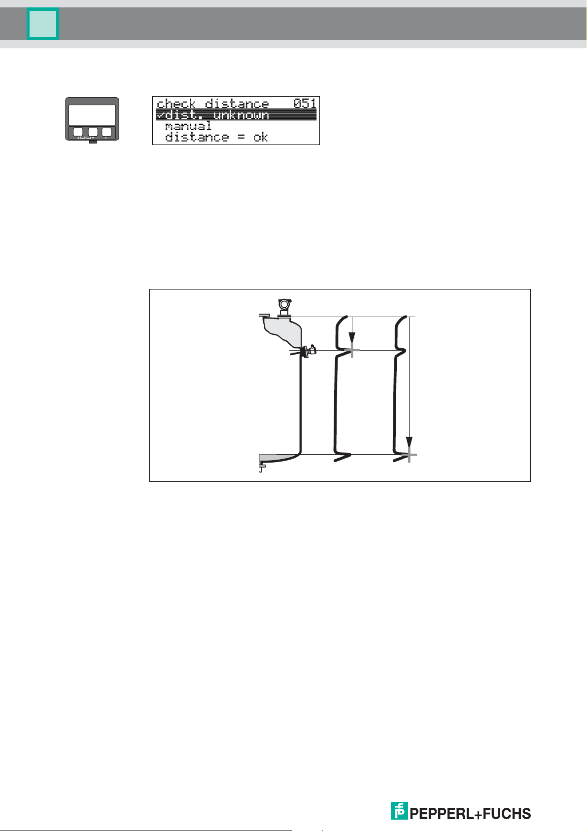
3.9 Function "check distance" (051)
–
+
E
This function triggers the mapping of interference echoes. To do so, the measured
distance must be compared with the actual distance to the product surface. The
following options are available for selection:
Selection:
• distance = ok
• dist. too small
• dist. too big
• dist. unknown
• manual
distance too small distance = ok
distance = ok
• Mapping is carried out up to the currently measured echo.
• The range to be suppressed is suggested in the "range of mapping" (052)
function.
Anyway, it is wise to carry out a mapping even in this case.
dist. too small
• At the moment, an interference is being evaluated.
• Therefore, a mapping is carried out including the presently measured echoes.
• The range to be suppressed is suggested in the "range of mapping" (052)
function.
dist. too big
• This error cannot be remedied by interference echo mapping.
• Check the application parameters (002), (003), (004) and "empty calibr." (005).
18
DOCT-0843A 01/2010 185572
Page 19
LUC-M** with HART/4 mA ... 20 mA and PROFIBUS PA
E
+
–
E
+
–
Function group "basic setup" (00)
dist. unknown
If the actual distance is not known, no mapping can be carried out.
manual
A mapping is also possible by manual entry of the range to be suppressed. This entry is
made in the "range of mapping" (052) function.
Caution!
"
The range of mapping must end 0.5 m (20 in) before the echo of the actual level. For an
empty tank, do not enter E, but E - 0.5 m (20 in).
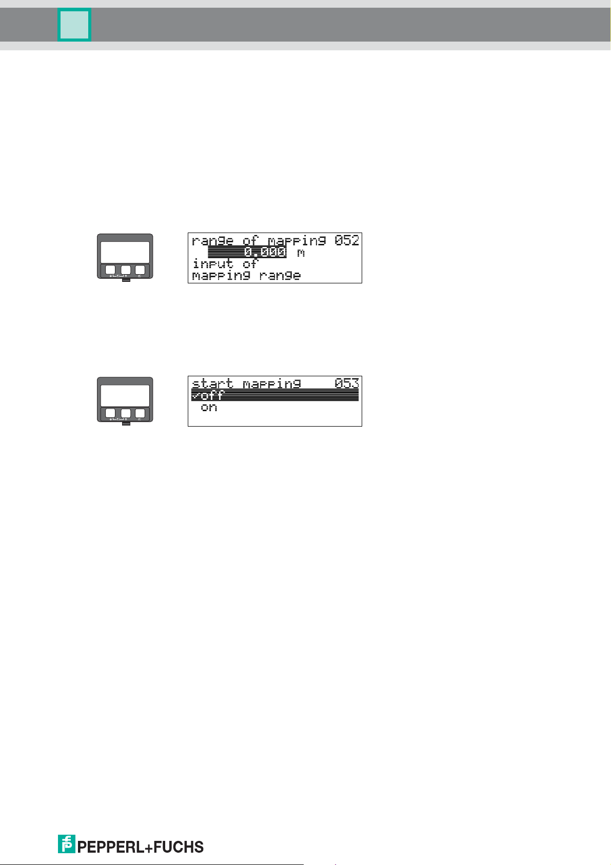
3.10 Function "range of mapping" (052)
This function displays the suggested range of mapping. The reference point is always
the sensor membrane. This value can be edited by the operator.
For manual mapping, the default value is: 0 m.
3.11 Funktion "start mapping" (053)
This function is used to start the interference echo mapping up to the distance given in
"range of mapping" (052).
Selection:
•off:no mapping is carried out
• on: mapping is started
Caution!
"
If a mapping already exists, it is overwriten up to the distance specified in
"range of mapping" (052). Beyond this value the existing mapping remains
unchanged.
DOCT-0843A 01/2010 185572
19
Page 20
LUC-M** with HART/4 mA ... 20 mA and PROFIBUS PA
Function group "basic setup" (00)
3.12 Display (008)
–
+
–
+
E
The distance measured from the reference point to the product surface and the level
calculated with the aid of the empty alignment are displayed again. Check whether the
values correspond to the actual level or the actual distance. The following cases can
occur:
• Distance correct – level correct basic setup completed.
• Distance incorrect – level incorrect a further interference echo mapping must be
carried out "check distance" (051).
• Distance correct – level incorrect check "empty calibr." (005).
E
After 3 s, the following message appears
!
Note!
After the basic setup, an evaluation of the measurement with the aid of the envelope
curve ("evelope curve" (0E) function group) is recommended.
20
DOCT-0843A 01/2010 185572
Page 21
LUC-M** with HART/4 mA ... 20 mA and PROFIBUS PA
E
+
–
E
+
–
3.6
(2.4)
(110 %)
(-10 %)
t
[mA]
22
-99999
t
HART
PROFIBUS PA
PROFIBUS PA
HART
(-10 %)
(110 %)
+99999
Function group "safety settings" (01)
4 Function group "safety settings" (01)
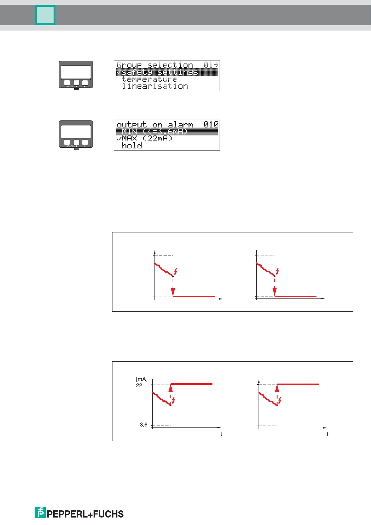
4.1 Function "output on alarm" (010)
This function is used to select the reaction of the device on an alarm.
Selection:
•MIN (≤ 3.6 mA)
• MAX (22 mA)
• hold
• user specific
MIN (≤ 3.6 mA)
If the instrument is in alarm state, the output changes as follows:
• HART: MIN alarm 3.6 mA (2.4 mA for 4-wire instruments)
• PROFIBUS PA: MIN alarm -99999
MAX (22 mA)
DOCT-0843A 01/2010 185572
If the instrument is in alarm state, the output changes as follows:
• HART: MAX alarm 22 mA
• PROFIBUS PA: MAX alarm +99999
21
Page 22
LUC-M** with HART/4 mA ... 20 mA and PROFIBUS PA
HART
t t
PROFIBUS PA
Hold Hold
3.6
-10 %
110 %
(110 %)
(-10 %)
[mA]
22
3.6
(-10 %)
(110 %)
Function group "safety settings" (01)
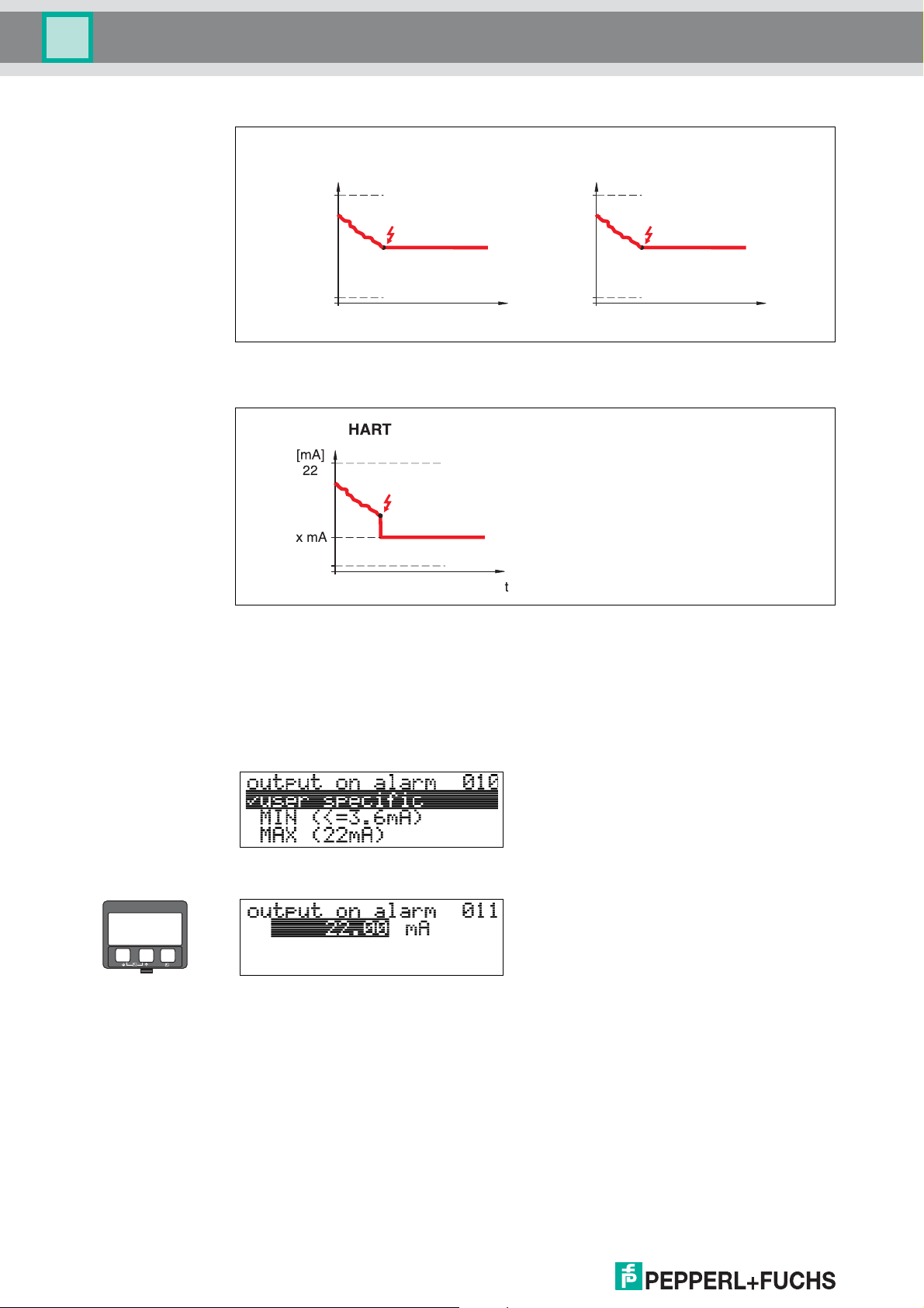
hold
If the instrument is in alarm state, the last measured value is held.
user specific
If the instrument is in an alarm state, the output is set to the value configured in
"output on alarm" (011) (x mA).
Caution!
"
This selection is available for HART devices only!
4.2 Function "output on alarm" (011), HART only
–
+
E
The current (in mA) which will be output in case of an alarm. This function is active when
you selected "user specific" in the "output on alarm" (010) function.
Caution!
"
This function is available for HART devices only!
22
DOCT-0843A 01/2010 185572
Page 23
LUC-M** with HART/4 mA ... 20 mA and PROFIBUS PA
E
+
–
delay time (014)
delay time (014)
delay time
(014)
ramp %span/min
(013)
Function group "safety settings" (01)
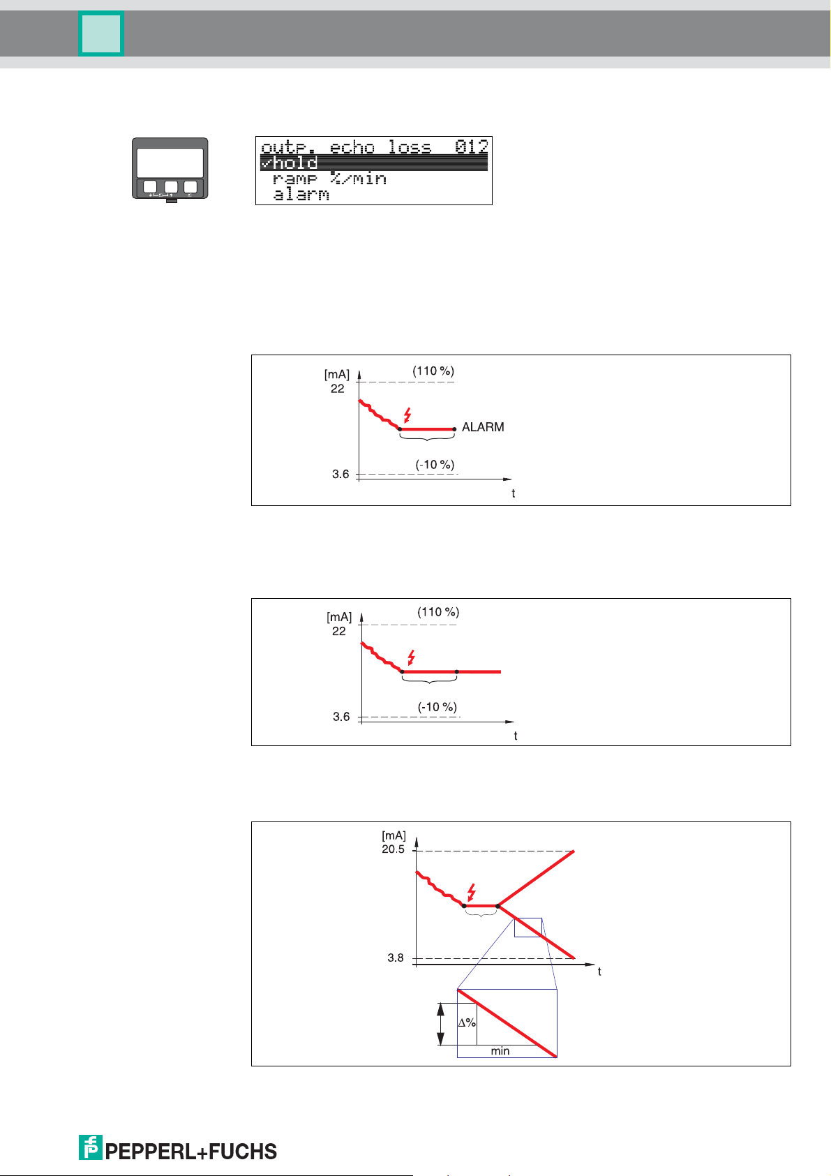
4.3 Function "outp. echo loss" (012)
Use this function to set the output response on echo loss.
Selection:
•alarm
• hold
•ramp %/min
alarm
On echo loss, the instrument switches to alarm state after an adjustable
"delay time" (014). The output response depends on the configuration set in
"output on alarm" (010).
hold
On echo loss, a warning is generated after a definable "delay time" (014). Output is
held.
ramp %/min
DOCT-0843A 01/2010 185572
On echo loss, a warning is generated after a definable "delay time" (014). The output is
changed towards 0 % or 100 % depending on the slope defined in "ramp %span/min"
(013).
23
Page 24

LUC-M** with HART/4 mA ... 20 mA and PROFIBUS PA
blocking dist.
(BD)
safety distance
(SD)
Function group "safety settings" (01)
4.4 Function "ramp %span/min" (013)
–
+
E
Ramp slope which defines the output value on echo loss. This value is used if
"ramp %span/min" is selected in "outp. echo loss" (012). The slope is given in % of
the measuring range per minute.
4.5 Function "delay time" (014)
–
+
E
Use this function to enter the delay time (default = 30 s) after which a warning is
generated on echo loss, or after which the instrument switches to alarm state.
4.6 Function "safety distance" (015)
A configurable safety distance is placed before the "blocking dist." (059) (page 40).
This distance warns you that any further level increase would make the measurement
invalid, because the blocking distance would be compromised.
24
E
–
+
Enter the size of the safety distance here. The default value is: 0.1 m.
DOCT-0843A 01/2010 185572
Page 25

LUC-M** with HART/4 mA ... 20 mA and PROFIBUS PA
E
+
–
WARNING
Function group "safety settings" (01)
4.7 Function "in safety dist." (016)
This function defines the response when the level enters the safety distance.
Selection:
•alarm
• warning
• self holding
alarm
Instrument enters the defined alarm state ("output on alarm" (011)). The alarm
message E651 – "level in safety distance - risk of overspill" is displayed.
If the level drops out of the safety distance, the alarm warning disappears and the
instrument starts to measure again.
warning
Instrument displays a warning E651 –"level in safety distance - risk of overspill", but
continues to measure. If the level leaves the safety distance, the warning disappears.
self holding
Instrument switches to defined alarm state ("output on alarm" (011)). The alarm
message E651 – "level in safety distance - risk of overspill" is displayed.
If the level leaves the safety distance, the measurement continues only after a reset of
the self holding (function: "ackn. alarm" (017)).
DOCT-0843A 01/2010 185572
25
Page 26

LUC-M** with HART/4 mA ... 20 mA and PROFIBUS PA
Function group "safety settings" (01)
4.8 Function "ackn. alarm" (017)
–
+
–
+
E
This function acknowledges an alarm in case of "self holding".
Selection:
•no
•yes
no
The alarm is not acknowledged.
yes
Acknowledgement takes place.
E
After 3 s, the following message appears
26
DOCT-0843A 01/2010 185572
Page 27

LUC-M** with HART/4 mA ... 20 mA and PROFIBUS PA
E
+
–
E
+
–
E
+
–
E
+
–
Function group "temperature" (03)
5 Function group "temperature" (03)
5.1 Function "measured temp." (030)
In this function the temperature at the sensor is displayed. The temperature unit is
determined by the function "temperature unit" (0C6).
5.2 Function "max. temp. limit" (031)
In this function the maximum permitted temperature of the sensor is displayed. The
temperature unit is determined by the function "temperature unit" (0C6). If this
temperature is exceeded, the sensor may become damaged.
5.3 Function "max. meas. temp." (032)
In this function the maximum temperature, which has ever been measured at the
senosr, is displayed. The temperature unit is determined by the function "temperature
unit" (0C6). This function is not influenced by a reset of the parameters.
DOCT-0843A 01/2010 185572
27
Page 28

LUC-M** with HART/4 mA ... 20 mA and PROFIBUS PA
Function group "temperature" (03)
5.4 Function "react high temp." (033)
–
+
E
In this function you determine, how the LUC-M** will react if the maximum permitted
temperature of the sensor is exceeded.
Selection:
• Warning
•Alarm
Warning
The instrument continues measuring. An error message is displayed.
Alarm
The current output adopts the value defined in the funcion "output on alarm" (010).
Additionally an error message is displayed.
5.5 Function "defect temp. sens." (034)
–
+
E
In this function you determine, how the LUC-M** will react, if the maximum permitted
temperature of the sensor is exceeded.
Selection:
• Warning
•Alarm
Warning
The instrument continues measuring. An error message is displayed.
Alarm
The current output adopts the value defined in the funcion "output on alarm" (010).
Additionally an error message is displayed.
–
+
E
After 3 s, the following message appears
28
DOCT-0843A 01/2010 185572
Page 29

LUC-M** with HART/4 mA ... 20 mA and PROFIBUS PA
E
+
–
E
+
–
ullage
level
Function group "linearisation" (04)
6 Function group "linearisation" (04)
6.1 Function "level/ullage" (040)
Selection:
• level CU
• level DU
• ullage CU
• ullage DU
level CU
!
Level in customer units. The measured value can be linearised.
The "linearisation" (041) default value is set to a linear 0 % ... 100 % .
level DU
Level in the selected "distance unit" (0C5).
ullage CU
Ullage in customer units. The value can be linearised.
The "linearisation" (041) default value is set to a linear 0 % ... 100 % .
ullage DU
Ullage in the selected "distance unit" (0C5).
Note!
Reference point for the ullage is "full calibr." (006) (= span).
DOCT-0843A 01/2010 185572
29
Page 30

LUC-M** with HART/4 mA ... 20 mA and PROFIBUS PA
Max. scale
= customer unit (042)
20 mA
4 mA
100 %
0 %
(046)
kg, m
3
,ft3, ...
Function group "linearisation" (04)
6.2 Function "linearisation" (041)
Linearisation defines the ratio of level to container volume or product weight and allows
a measurement in customer units, e. g. metres, hectolitres etc. The measured value in
"measured value" (000) is then displayed in the selected unit.
–
+
E
This function is used to select the linearisation modes.
Selection:
• linear
• horizontal cyl
• manual
• semi-automatic
• table on
• clear table
linear
The tank is linear e. g. a cylindrical vertical tank. You can measure in customer units by
entering a maximum volume/weight.
You can select the "customer unit" (042). Define the volume value corresponding to
the calibration in "max. scale" (046). This value corresponds to an output
of 100 % (= 20 mA for HART).
30
DOCT-0843A 01/2010 185572
Page 31

LUC-M** with HART/4 mA ... 20 mA and PROFIBUS PA
Max. scale
= customer unit (042)
diameter vessel (047)
100 %
20 mA
0 %
4 mA
kg,m3,ft3, ...
(046)
= customer unit (042)
kg, m
3
,ft3, ...
100 %
20 mA
0 %
4 mA
(2)
(4)
(3)
Function group "linearisation" (04)
horizontal cyl
The volume, mass etc. are calculated automatically in cylindrical horizontal tanks by
entering the "diameter vessel" (047), the "customer unit" (042) and the
"max. scale" (046). The "max. scale" (046) corresponds to an output
of 100 % (= 20 mA for HART).
manual
If the level is not proportional to the volume or weight within the set measuring range,
you can enter a linearisation table in order to measure in customer units. The
requirements are as follows:
• The 32 (max.) value pairs for the linearisation curve points are known.
• The level values must be given in ascending order. The curve is monotonously
increasing.
• The level heights for the first and last points on the linearisation curve correspond
to empty and full calibration respectively.
• The linearisation takes place in the basic setup unit ("distance unit" (0C5)).
DOCT-0843A 01/2010 185572
!
Each point (2) in the table is described by a value pair: level (3) and, for example,
volume (4). The last value pair defines the 100 % output (= 20 mA for HART).
Note!
The manual linearisation mode can also be used for flow measurements. To do this,
simply enter the respective flow level (instead of the volume) into the table. You can find
the appropriate flow values in the Q/h table of your channel or weir.
31
Page 32

LUC-M** with HART/4 mA ... 20 mA and PROFIBUS PA
Function group "linearisation" (04)
–
+
E
Select the table point (point 1).
Enter the level belonging to point 1.
Enter the corresponding volume.
!
!
Enter a further table point?
Next table point.
Continue until "next point" (045) is answered
Note!
After making entries into the table, activate it with "table on".
The 100 % value (= 20 mA for HART) is defined by the last point in the table.
Note!
Before confirming 0.00 m as the level or 0.00% as the volume, activate the edit mode
with
O or S.
...
with no.
32
DOCT-0843A 01/2010 185572
Page 33

LUC-M** with HART/4 mA ... 20 mA and PROFIBUS PA
E
+
–
Function group "linearisation" (04)
semi-automatic
The tank is filled in stages when the linearisation curve is entered semi-automatically.
The LUC-M** automatically detects the level and the corresponding volume/weight has
to be entered.
The procedure is similar to manual table entry, where the level value for each table point
is given automatically by the instrument.
!
!
Note!
If the tank is emptied (out litres), pay attention to the following points:
• The number of points must be known in advance.
• The first table number = (32 – number of points).
•Entries in "Tab. no." (043) are made in reverse order (last entry = 1).
table on
An entered linearisation table only becomes effective when activated.
clear table
Before making entries into the linearisation table, any existing tables must be deleted.
The linearisation mode automatically switches to linear.
Note!
A linearisation table can be deactivated by selecting "linear" or "horizontal cyl" (or the
"level/ullage" (040) function = "level DU", "ullage DU"). It is not deleted and can be
reactivated at any time by selecting "table on".
6.3 Function "customer unit" (042)
You can select the customer unit with this function.
Selection:
•%
• Volume: l, hl, m3,
• Weight: kg, t, lb, ton
• Length: m, ft, mm, inch
• Flow: l/s, l/min, l/h, m3/s, m3/min, m3/h, ft3/s, gal/s, gal/m, gal/hr, mgal/d,
igal/s, igal/min, igal/h
Dependence
The units of the following parameters are changed:
• "measured value" (000)
• "input volume" (045)
• "max. scale" (046)
• "simulation value" (066)
dm3, cm3, ft3, usgal, igal
DOCT-0843A 01/2010 185572
33
Page 34

LUC-M** with HART/4 mA ... 20 mA and PROFIBUS PA
Function group "linearisation" (04)
6.4 Function "table no." (043)
–
+
E
Position of the value pair in the linearisation table.
Dependence
Updates "input level" (044) , "input volume" (045).
6.5 Function "input level" (044)
–
+
E
You can enter the level for each point of the linearisation curve with this function. When
the linearisation curve is entered semi-automatically, LUC-M** detects the level
automatically.
34
User input:
Level in "distance unit" (0C5).
DOCT-0843A 01/2010 185572
Page 35

LUC-M** with HART/4 mA ... 20 mA and PROFIBUS PA
E
+
–
E
+
–
E
+
–
Function group "linearisation" (04)
6.6 Function "input volume" (045)
Specify the volume for each point of the linearisation curve with this function.
User input:
Volume in "customer unit" (042).
6.7 Function "max. scale" (046)
You can enter the end value of the measuring range with this function. This input is
necessary if you selected "linear" or "horizontal cyl" in the "linearisation" (041)
function.
6.8 Function "diameter vessel" (047)
Enter the tank diameter with this function. This entry is necessary if you selected
"horizontal cyl" in the "linearisation" (041) function.
DOCT-0843A 01/2010 185572
35
Page 36

LUC-M** with HART/4 mA ... 20 mA and PROFIBUS PA
distance too small distance = ok
Function group "extended calibr." (05)
7 Function group "extended calibr." (05)
–
+
E
7.1 Function "selection" (050)
–
+
E
Select the function of the extended calibration.
Selection:
• common
leads to the functions "echo quality" (056), "offset" (057),
"output damping" (058) and "blocking distance" (059)
• mapping
leads to the functions for an interference echo suppression (tank map):
(051) ... (053)
• extended map
leads to the functions "pres. map. dist." (054) and "cust. tank map" (055)
7.2 Function "check distance" (051)
–
+
E
This function triggers the mapping of interference echoes. To do so, the measured
distance must be compared with the actual distance to the product surface. The
following options are available for selection:
Selection:
• distance = ok
• dist. too small
• dist. too big
• dist. unknown
• manual
36
DOCT-0843A 01/2010 185572
Page 37

LUC-M** with HART/4 mA ... 20 mA and PROFIBUS PA
E
+
–
E
+
–
Function group "extended calibr." (05)
distance = ok
• Mapping is carried out up to the currently measured echo.
• The range to be suppressed is suggested in the "range of mapping" (052)
function.
Anyway, it is wise to carry out a mapping even in this case.
dist. too small
• At the moment, an interference is being evaluated.
• Therefore, a mapping is carried out including the presently measured echoes.
• The range to be suppressed is suggested in the "range of mapping" (052)
function.
dist. too big
• This error cannot be remedied by interference echo mapping.
• Check the application parameters (002), (003), (004) and "empty calibr." (005).
dist. unknown
If the actual distance is not known, no mapping can be carried out.
manual
A mapping is also possible by manual entry of the range to be suppressed. This entry is
made in the "range of mapping" (052) function.
Caution!
"
The range of mapping must end 0.5 m (20 in) before the echo of the actual level. For an
empty tank, do not enter E, but E - 0.5 m (20 in).
7.3 Function "range of mapping" (052)
This function displays the suggested range of mapping. The reference point is always
the sensor membrane. This value can be edited by the operator.
For manual mapping, the default value is: 0 m.
7.4 Function "start mapping" (053)
This function is used to start the interference echo mapping up to the distance given in
"range of mapping" (052).
Selection:
•off:no mapping is carried out
• on: mapping is started
Caution!
"
If a mapping already exists, it is overwriten up to the distance specified in
"range of mapping" (052). Beyond this value the existing mapping remains
unchanged.
DOCT-0843A 01/2010 185572
37
Page 38

LUC-M** with HART/4 mA ... 20 mA and PROFIBUS PA
pres. map dist. (054)
Function group "extended calibr." (05)
7.5 Function "pres. map dist." (054)
–
+
E
Displays the distance up to which a mapping has been recorded.
A value of 0 indicates that no mapping was recorded so far.
7.6 Function "cust. tank map" (055)
–
+
E
This function displays the evaluation mode using the customer tank map.
Selection:
• inactive
•active
• reset
inactive
No tank mapping has been recorded, or map is switched off. Evaluation is only using
FAC (see page 64).
active
Evaluation is using the customer tank map (see page 63).
reset
Deletes the complete tank map.
38
DOCT-0843A 01/2010 185572
Page 39

LUC-M** with HART/4 mA ... 20 mA and PROFIBUS PA
E
+
–
echo quality (056)
20 mA
100 %
4 mA
0 %
E
+
–
E
+
–
Function group "extended calibr." (05)
7.7 Function "echo quality" (056)
The echo quality is the benchmark for measurement reliability. It describes the amount
of reflected energy and depends primarily on the following conditions:
• Surface characteristics (waves, foam etc.)
• Distance between sensor and product
Low values increase the probability that the echo is lost through a change in
measurement conditions, e. g. turbulent surface, foam, large measuring distance.
7.8 Function "offset" (057)
This function corrects the measured level by a constant value. The entered value is
added to the measured level.
7.9 Function "output damping" (058)
Influences the time an output requires to react to a sudden level jump (63% of steady
state). A high value attenuates, for example, the influences of rapid changes on the
measured variable.
User input:
0 s ... 255 s
The default value depends on the selected application parameters "tank shape" (002),
"medium property" (003) and "process cond." (004).
DOCT-0843A 01/2010 185572
39
Page 40

LUC-M** with HART/4 mA ... 20 mA and PROFIBUS PA
Function group "extended calibr." (05)
7.10 Function "blocking dist." (059)
–
+
–
+
E
In this function the blocking distance is displayed. Level echoes within the blocking
distance can not be detected by the LUC-M**. Make sure that the maximum level will
never run into the blocking distance.
E
After 3 s, the following message appears
40
DOCT-0843A 01/2010 185572
Page 41

LUC-M** with HART/4 mA ... 20 mA and PROFIBUS PA
E
+
–
E
+
–
E
+
–
E
+
–
E
+
–
Function group "output" (06) and "profibus param." (06)
8 Function group "output" (06) and
"profibus param." (06)
Display at HART instrument
Display at PROFIBUS PA instrument
8.1 Function "commun. address" (060), HART only
Enter the communication address for the instrument with this function.
Selection:
• Standard: 0
• Multidrop: 1 ... 15
The output current is constant at 4 mA in multidrop mode.
Caution!
"
This function is available for HART devices only!
8.2 Function "instrument addr." (060),
PROFIBUS PA only
The PA bus address is displayed in this field. The address is set either directly on the
instrument using DIP switches (see instrument operating instructions).
Caution!
"
This function is available for PROFIBUS PA devices only!
8.3 Function "no. of preambels" (061), HART only
Enter the number of preambles for the HART protocol with this function.
An increase in the value is advisable for "bad" lines with communications problems.
Caution!
"
This user input is available for HART devices only!
DOCT-0843A 01/2010 185572
41
Page 42

LUC-M** with HART/4 mA ... 20 mA and PROFIBUS PA
Output
off
on
Function group "output" (06) and "profibus param." (06)
8.4 Function "ident number" (061), PROFIBUS PA only
–
+
E
Selection:
• manufacturer
•profile
manufacturer
Set to152C hex according to manufacturer (PNO registered).
profile
Setting defined as in PA Profile 3.0: 9700 hex - instrument with one AI block.
Caution!
"
This function is available for PROFIBUS PA devices only!
8.5 Function "thres. main val." (062), HART only
–
+
E
The output of negative level values can be suppressed with this function.
Selection:
•off:minimum output -10 % (3.8 mA for HART)
• on: minimum output 0 % (4 mA for HART)
Caution!
"
This user input is available for HART devices only!
42
DOCT-0843A 01/2010 185572
Page 43

LUC-M** with HART/4 mA ... 20 mA and PROFIBUS PA
E
+
–
E
+
–
curr. turn down
fixed current
standard
[mA]
20
[mA]
20
4
100 [%]0
4
100 [%]0
Function group "output" (06) and "profibus param." (06)
8.6 Function "set unit to bus" (062), PROFIBUS PA only
Selection:
•confirm
After confirming this function, the unit of the measured variable is taken over in
the AI block (PV scale Out scale).
This function must always be executed after changing the unit.
Caution!
"
This function is available for PROFIBUS PA devices only!
8.7 Function "curr. output mode" (063), HART only
In this function you specify the mode of the current output.
Selection:
• standard
• curr. turn down
•fixed current
standard
The total measuring range (0 % ... 100 %) will be mapped to the current intervall
(4 mA ... 20 mA).
curr. turn down
Only a part of the measuring range will be mapped to the current intervall
(4 mA ... 20 mA).
Use the functions "4 mA value" (068) and "20 mA value" (069) to define the
concerning range.
fixed current
The current is fixed. The measured value is transmitted by the HART signal only. The
DOCT-0843A 01/2010 185572
value of the current is defined in the "fixed current" (064) function.
Caution!
"
This function is active for HART devices only!
43
Page 44

LUC-M** with HART/4 mA ... 20 mA and PROFIBUS PA
Function group "output" (06) and "profibus param." (06)
8.8 Function "out value" (063), PROFIBUS PA only
–
+
E
This displays the AI block output.
Caution!
"
This function is available for PROFIBUS PA devices only!
8.9 Function "fixed cur. value" (064), HART only
–
+
E
Set the fixed current value with this function. This entry is necessary when you have
switched on the "fixed current" (063) function.
User input:
3.8 mA ... 20.5 mA
Caution!
"
This user input is available for HART devices only!
8.10 Function "out status" (064), PROFIBUS PA only
–
+
E
Displays the current output status (for value, see operating instructions of relevant
instrument).
Caution!
"
This function is available for PROFIBUS PA devices only!
44
DOCT-0843A 01/2010 185572
Page 45

LUC-M** with HART/4 mA ... 20 mA and PROFIBUS PA
E
+
–
sim. current
(HART only)
sim. volume
sim. level
0 % ... 100 %
4 mA ... 20 mA
E
+
–
Function group "output" (06) and "profibus param." (06)
8.11 Function "simulation" (065)
If necessary, linearisation, the output signal and the current output can be tested with
the simulation function. You have the following simulation options:
Selection:
• sim. off
•sim. level
•sim. volume
• sim. current (HART only)
DOCT-0843A 01/2010 185572
sim. off
Simulation is switched off.
sim. level
Enter the level value in "simulation value" (066).
The functions:
• "measured value" (000)
• "measured level" (0A6)
• "output current" (067) – only with HART instruments!
follow the entered values.
sim. volume
Enter the volume value in "simulation value" (066).
The functions
• "measured value" (000)
• "output current" (067) – only with HART instruments!
follow the entered values.
sim. current (HART only)
Enter the current value in "simulation value" (066).
The function
• "output current" (067) – only with HART instruments!
follows the entered values.
45
Page 46

LUC-M** with HART/4 mA ... 20 mA and PROFIBUS PA
Function group "output" (06) and "profibus param." (06)
8.12 Function "simulation value" (066)
After selecting the "sim. level" option in the
"simulation" (065) function, the following
–
+
–
+
–
+
E
E
E
8.13 Function "output current" (067), HART only
message appears in the display: you can enter
the level.
After selecting the "sim. volume" option in the
"simulation" (065) function, the following
message appears in the display: you can enter
the volume.
After selecting the "sim. current" option in the
"simulation" (065) function, the following
message appears in the display: Enter the
output current (only for HART instruments).
–
+
E
Displays the output current in mA.
Caution!
"
This function is available for HART devices only!
8.14 Function "2nd cyclic value" (067), PROFIBUS PA only
–
+
E
Selects the second cyclical value.
Selection:
• height/dist.
•temperature
The LUC-M** always transmits the distance as the second cyclical value.
Caution!
"
This function is available for PROFIBUS PA devices only!
46
8.15 Function "4mA value" (068), HART only
–
+
E
In this function specify the level (or volume, weight, flow resp.), at which the output
current should be 4 mA. This value will be used if you choose the option
"curr. turn down" in the "current output mode" (063) function.
DOCT-0843A 01/2010 185572
Page 47

LUC-M** with HART/4 mA ... 20 mA and PROFIBUS PA
E
+
–
E
+
–
E
+
–
Function group "output" (06) and "profibus param." (06)
8.16 Function "select v0h0" (068), PROFIBUS PA only
Selects the value displayed in "measured value" (000).
Selection:
• measured value
• display value
measured value
The configured measured value is displayed in the "measured value" (000) function.
display value
The value in "display value" (069) is displayed in the "measured value" (000)
function.
Caution!
"
This function is available for PROFIBUS PA devices only!
8.17 Function "20mA value" (069), HART only
In this function specify the level (or volume, weight, flow resp.), at which the output
current should be 20 mA. This value will be used if you choose the option
"curr. turn down" in the "current output mode" (063) function.
8.18 Function "display value" (069), PROFIBUS PA only
This field can be set externally, e. g. from a PLC. The value is then displayed as the
main measured variable in the display by selecting the
"select v0h0" (068) = "display value" function.
Caution!
"
This function is available for PROFIBUS PA devices only!
DOCT-0843A 01/2010 185572
47
Page 48

LUC-M** with HART/4 mA ... 20 mA and PROFIBUS PA
Function group "envelope curve" (0E)
9 Function group "envelope curve" (0E)
–
+
E
9.1 Function "plot settings" (0E1)
–
+
E
Here select which information is displayed in the LCD:
Selection:
• envelope curve
• env.curve+FAC (on FAC see page 64)
• env.curve+cust.map (i. e. customer tank map is also displayed, see page 63)
9.2 Function "recording curve" (0E2)
This function defines whether the envelope curve is read as a
• single curve
or
• cyclic.
E
!
Note!
If the cyclical envelope curve is active in the display, the measured variable is refreshed
in a slower cycle time. It is therefore recommended to exit the envelope curve display
after optimising the measuring point.
–
+
48
DOCT-0843A 01/2010 185572
Page 49

LUC-M** with HART/4 mA ... 20 mA and PROFIBUS PA
Min. distance
of the plot
Max. distance
of the plot
Distance of
evaluated echo
Interference echo
Evaluated echo
is marked
Quality of
evaluated echo
Empty calibr.
Full calibr.
Envelope curve
only
Envelope curve
and
interference echo
suppression (map)
Level echo
Map
...
Move mode:
- move to the left
- move to the right
Horizontal Zoom mode:
- horizontal zoom in
- horizontal zoom out
Vertical Zoom mode:
- vertical zoom
(4 steps)
Function group "envelope curve" (0E)
9.3 Function "envelope curve display" (0E3)
The envelope curve is displayed in this function. You can use it to obtain the following
information:
DOCT-0843A 01/2010 185572
Navigating in the envelope curve display
Using navigation, the envelope curve can be scaled horizontally and vertically and
shifted to the left or the right. The active navigation mode is indicated by a symbol in the
top left hand corner of the display.
Horizontal Zoom mode
Press
Zoom mode. Either or is displayed.
You now have the following options:
•
•
or to switch to the envelope curve navigation. You are then in Horizontal
increases the horizontal scale.
reduces the horizontal scale.
S
O
49
Page 50

LUC-M** with HART/4 mA ... 20 mA and PROFIBUS PA
Function group "envelope curve" (0E)
Move mode
Then press
You now have the following options:
•
shifts the curve to the right.
•
shifts the curve to the left.
to switch to Move mode. Either or is displayed.
S
Vertical Zoom mode
Press
once more to switch to Vertical Zoom mode. is displayed.
You now have the following options:
•
increases the vertical scale.
reduces the vertical scale.
•
The display icon shows the current zoom factor ( to ).
S
Exiting the navigation
•Press
•Press
again to run through the different modes of the envelope curve navigation.
and to exit the navigation. The set increases and shifts are retained.
Only when you reactivate the "recording curve" (0E2) function does the
LUC-M** use the standard display again.
O
O
50
DOCT-0843A 01/2010 185572
Page 51

LUC-M** with HART/4 mA ... 20 mA and PROFIBUS PA
E
+
–
E
+
–
E
+
–
Function group "display" (09)
10 Function group "display" (09)
10.1 Function "language" (092)
Selects the display language.
Selection:
• English
•Deutsch
• Français
• Español
• Italiano
• Nederlands
Dependence
All texts are changed.
10.2 Function "back to home" (093)
If no entry is made using the display during the specified time period, the display returns
to the measured value display.
9999 s means that there is no return.
User input:
3 s ... 9999 s
DOCT-0843A 01/2010 185572
51
Page 52

LUC-M** with HART/4 mA ... 20 mA and PROFIBUS PA
Function group "display" (09)
10.3 Function "format display" (094)
–
+
E
Selects the display format.
Selection:
• decimal
•1/16''
decimal
The measured value is given in decimal form in the display (e. g. 10.70 %).
1/16''
The measured value is given in the display in this format (e. g 5'05-14/16").
This option is only possible for "distance unit" (0C5) – "ft" and "in"!
10.4 Function "no.of decimals" (095)
–
+
E
Selection:
•x
•x.x
•x.xx
• x.xxx
10.5 Function "sep. character" (096)
–
+
E
Selection:
•.The decimal place is separated by a point.
• , The decimal place is separated by a comma.
10.6 Function "display test" (097)
–
+
E
52
All display pixels are switched on. If the whole LCD is dark, it is working correctly.
DOCT-0843A 01/2010 185572
Page 53

LUC-M** with HART/4 mA ... 20 mA and PROFIBUS PA
E
+
–
E
+
–
E
+
–
E
+
–
Function group "diagnostics" (0A)
11 Function group "diagnostics" (0A)
In the "diagnostics" (0A) function group, you can display and confirm error messages.
Type of error
Errors that occur during commissioning or measuring are displayed immediately on the
local display. If two or more system or process errors occur, the error with the highest
priority is the one shown on the display.
The measuring system distinguishes between two types of error:
• A (Alarm):
Instrument goes into a defined state (e. g. MAX)
Indicated by a constant
(For a description of the codes, see page 66)
• W (Warning):
Instrument continue measuring, error message is displayed.
Indicated by a flashing
(For a description of the codes, see page 66)
• E (Alarm/Warning):
Configurable (e. g. loss of echo, level within the safety distance)
Indicated by a constant/flashing
(For a description of the codes, see page 66)
symbol.
symbol.
symbol.
11.1 Function "present error" (0A0)
The present error is shown using this function.
11.2 Function "previous error" (0A1)
The last error presented is shown with this function.
11.3 Function "clear last error" (0A2)
Selection:
•keep
•erase
Caution!
"
This function can be performed on the display only!
DOCT-0843A 01/2010 185572
53
Page 54

LUC-M** with HART/4 mA ... 20 mA and PROFIBUS PA
Function group "diagnostics" (0A)
11.4 Function "reset" (0A3)
Caution!
"
A reset sets the instrument back to the factory settings. This can lead to an impairment
of the measurement. Generally, you should perform a basic setup again following a
reset.
A reset is only necessary:
• if the instrument no longer functions
• if the instrument must be moved from one measuring point to another
• if the instrument is being de-installed/put into storage/installed
–
+
E
Entry ("reset" (0A3)):
• 333 = customer parameters (HART)
• 33333 = customer parameters (PROFIBUS PA)
This reset is recommended whenever an instrument with an unknown "history" is to be
used in an application:
• The LUC-M** is reset to the default values.
• The customer specific tank map is not deleted.
• A linearisation is switched to "linear" although the table values are retained. The
table can be reactivated in the "linearisation" (04) function group.
List of functions that are affected by a reset:
• "tank shape" (002)
• "empty calibr." (005)
• "full calibr." (006)
• "output on alarm" (010)
• "output on alarm" (011)
• "outp. echo loss" (012)
•"ramp %span/min" (013)
•"delay time" (014)
• "safety distance" (015)
• "in safety dist." (016)
• "level/ullage" (040)
• "linearisation" (041)
• "customer unit" (042)
• "diameter vessel" (047)
• "range of mapping" (052)
• "pres. Map dist" (054)
• "offset" (057)
• "low output limit" (062)
• "fixed current" (063)
• "fixed cur. value" (064)
• "simulation" (065)
• "simulation value" (066)
• "format display" (094)
• "distance unit" (0C5)
• "download mode" (0C8)
54
The tank map can also be reset in the "cust. tank map" (055) function of the
"extended calibr." (05) function group.
This reset is recommended whenever an instrument with an unknown "history" is to be
used in an application or if a faulty mapping was started:
• The tank map is deleted. The mapping must be recommenced.
DOCT-0843A 01/2010 185572
Page 55

LUC-M** with HART/4 mA ... 20 mA and PROFIBUS PA
E
+
–
E
+
–
Function group "diagnostics" (0A)
11.5 Function "unlock parameter" (0A4)
Set-up can be locked and unlocked with this function.
11.5.1 Locking of the configuration mode
The LUC-M** can be protected in two ways against unauthorised changing of
instrument data, numerical values or factory settings:
"unlock parameter" (0A4):
A value <> 100 for HART (e. g. 99) or < > 2457 for PROFIBUS PA (e. g. 2456) must be
entered in "unlock parameter" (0A4) in the "diagnostics" (0A) function group. The
lock is shown on the display by the
display or by communication.
Hardware lock:
The instrument is locked by pressing the
The lock is shown on the display by the
via the display by pressing the
possible to unlock the hardware by communication.
All parameters can de displayed even if the instrument is locked.
symbol and can be released again either via the
O and S and F keys at the same time.
symbol and can only be unlocked again
O and S and F keys at the same time again. It is not
O and S and F press simultaneous.
The LOCK_SYMBOL appears on the LCD.
DOCT-0843A 01/2010 185572
55
Page 56

LUC-M** with HART/4 mA ... 20 mA and PROFIBUS PA
Function group "diagnostics" (0A)
11.5.2 Unlocking of configuration mode
If an attempt is made to change parameters when the instrument is locked, the user is
automatically requested to unlock the instrument:
"unlock parameter" (0A4):
By entering the unlock parameter (on the display or via communication)
100 = for HART devices
2457 = for PROFIBUS PA Fieldbus devices
the LUC-M** is released for operation.
Hardware lock:
After pressing the
unlock parameter
100 = for HART devices
2457 = for PROFIBUS PA devices.
O and S and F keys at the same time, the user is asked to enter the
–
+
E
O and S and F press simultaneous.
Please enter unlock code and confirm with F.
Caution!
"
Changing certain parameters such as all sensor characteristics, for example, influences
numerous functions of the entire measuring system, particularly measuring accuracy.
There is no need to change these parameters under normal circumstances and
consequently, they are protected by a special code known only to the P+F service
organization. Please contact Pepperl+Fuchs if you have any questions.
56
11.6 Function "measured dist." (0A5)
–
+
E
Display of measured distance in the selected "distance unit" (0C5).
DOCT-0843A 01/2010 185572
Page 57

LUC-M** with HART/4 mA ... 20 mA and PROFIBUS PA
E
+
–
A
Measured
distance
Measured
level
20 mA
100 %
4m
0 %
E
+
–
Function group "diagnostics" (0A)
11.7 Function "measured level" (0A6)
Display of measured level in the selected "distance unit" (0C5).
11.8 Function "detection window" (0A7)
Is used to switch the detection window on and off and to reset an existing detection
window.
If this function is switched on, a window is defined surrounding the current level echo
(typical width: 1 m ... 2.5 m; depending on the application parameters). The window
always moves togehter with a rising a falling echo.
Echos beyond the limits of the window are ignored for a certain time.
Selection:
•off
•on
•reset
After selection of this option, the current window is reset, the level echo is looked for
in the complete measuring range and a new window is defined surrounding the
current level echo.
57
DOCT-0843A 01/2010 185572
Page 58

LUC-M** with HART/4 mA ... 20 mA and PROFIBUS PA
Function group "diagnostics" (0A)
11.9 Function "application par." (0A8)
–
+
–
+
E
Displays whether or not one of the settings dependent on the "tank shape" (002),
"medium property" (003) and "process cond." (004) application parameters has
been changed or not.
If, for example, the "output damping" (058) is changed, the
"application par." shows "modified".
Display:
• not modified
•modified
E
After 3 s, the following message appears
58
DOCT-0843A 01/2010 185572
Page 59

LUC-M** with HART/4 mA ... 20 mA and PROFIBUS PA
E
+
–
E
+
–
E
+
–
E
+
–
Function group "system parameters" (0C)
12 Function group "system parameters" (0C)
12.1 Function "tag no." (0C0)
You can define the tag number with this function.
User input:
• 16 alphanumeric characters for HART instruments (8 using the HART universal
command)
• 32 alphanumeric characteristics for PROFIBUS PA instruments
12.2 Function "Profile Version" (0C1), PROFIBUS PA only
The PA profile version is shown using this function (Profile 3.0).
Caution!
"
This function is available for PROFIBUS PA devices only!
12.3 Function "protocol+sw-no." (0C2)
This function shows the protocol and the hardware and software version: Vxx.yy.zz.prot.
Display:
xx: hardware version
yy: software version
zz: software revision
prot: protocoll type (e. g. HART)
DOCT-0843A 01/2010 185572
59
Page 60

LUC-M** with HART/4 mA ... 20 mA and PROFIBUS PA
Function group "system parameters" (0C)
12.4 Function "serial no." (0C4)
–
+
E
This function displays the instrument serial number.
12.5 Function "distance unit" (0C5)
–
+
E
You can select the basic distance unit with this function.
Selection:
•m
•ft
•mm
•inch
Dependence
m, mm: "format display" (094) can only be "decimal".
The units are changed for the following parameters:
• "empty calibr." (005)
• "full calibr." (006)
• "safety distance" (015)
• "input level" (044)
• "diameter vessel" (047)
• "range of mapping" (052)
• "cust. tank map" (055)
• "offset (057)"
• "simulation value" (066)
• "measured dist." (0A5)
• "measured level" (0A6)
60
DOCT-0843A 01/2010 185572
Page 61

LUC-M** with HART/4 mA ... 20 mA and PROFIBUS PA
E
+
–
E
+
–
E
+
–
Function group "service" (0D)
12.6 Function "temperature unit" (0C6)
In this function you select the temperature unit.
Selection:
•°F
•°C
The unit is changed for the following functions
• "measured temp." (030)
• "max. temp. limit" (031)
• "max. meas. temp" (032)
12.7 Function "download mode" (0C8)
This parameter defines which values are written to the instrument during a configuration
download.
Selection:
• parameter only
• param+cust.map
• mapping only
After 3 s, the following message appears
13 Function group "service" (0D)
This function group is reserved for service purposes only.
DOCT-0843A 01/2010 185572
61
Page 62

LUC-M** with HART/4 mA ... 20 mA and PROFIBUS PA
y
x
Sending pulse with
reverberation time
Interference echo
caused by
installations
Interference echo
caused
Interference echoes
caused by
installations
Level echo
Time-of-flight
Amplitude
by agitator
Signal evaluation
14 Signal evaluation
14.1 Envelope curve
The echo of an ultrasonic impulse does not only contain the desired echo from the
product surface, but also interference echoes (e. g. from tank fittings or multiple
reflections). In order to identify these echoes one plots the logarithmic amplitude of the
echo versus the time-of-flight of the ultrasonic impulse. This plot is called envelope
curve.
The envelope curve can be displayed in the "envelope curve" (0E) function group (see
page 48).
62
DOCT-0843A 01/2010 185572
Page 63

LUC-M** with HART/4 mA ... 20 mA and PROFIBUS PA
Customer tank map
operation in
and "extented calibration"
"basic setup"
Envelope curve with reflections/echoes in the tank
Interference echoes
Level echo
[dB]
[m]
0
20
40
60
80
100
120
Signal evaluation
14.2 Interference echo suppression (tank mapping)
The interference echo suppression of the LUC-M** makes sure that interference echoes
are not interpreted as the level echo by fault.
In order to carry out the interference echo suppression one must record a time-of-flight
dependent threshold (TDT), which is also called the tank map. All maxima of the
envelope curve which are situated below the TDT are discarded by the signal evaluation
procedures.
It is recommended to record the tank map when the vessel is as possible empty. Then,
the map will include all echoes except the level echo.
But even, if it is not possible to empty the vessel during the commissioning of the
LUC-M**, you should perform the map. In this case it is recommended to repeat the
record of the mapping at a later time – when the vessel is as possible empty.
The tank map is recorded in the function group "extended calibration" (05). Select the
option "mapping" in the "selection" (050) function.
DOCT-0843A 01/2010 185572
63
Page 64

LUC-M** with HART/4 mA ... 20 mA and PROFIBUS PA
Echoes
The echo with the greatest distance
to the FAC will be evaluated.
0
20
40
60
80
100
120
[dB]
[m]
FAC
Envelope curve with reflections/echoes in the tank
Signal evaluation
14.3 Floating Average Curve (FAC)
The function of the Floating Average Curve (FAC) is similar to the interference echo
suppression.
The main difference is, that the tank map is recorded only once whilst the FAC adjusts
itself continuously to the changing measuring conditions.
By this procedure changes of the interference echoes (e. g. by build-up) can be
compensated for.
In contrast to the tank map, the FAC can only register small interference echoes.
The FAC is always used in the signal evaluation, even if the tank map has been
deactivated.
In the envelope curve, the maximum with the largest distance to the FAC is interpreted
as the level echo.
DOCT-0843A 01/2010 185572
64
Page 65

LUC-M** with HART/4 mA ... 20 mA and PROFIBUS PA
Trouble shooting
15 Trouble shooting
15.1 System error messages
Current error
Errors which the LUC-M** detects during commissioning or operation are displayed:
• In the "measured value" (000) function
• In the "diagnostics" (0A) function group in the "present error" (0A0) function
(only the highest priority error is displayed; in the case of multiple errors, you can
scroll between the different error messages by pressing
Last error
The last error is displayed in the "diagnostics" (0A) function group in the
"previous error" (0A1) function. This display can be deleted in the
"clear last error" (0A2) function.
Types of errors
Type of error Symbol Meaning
The output signal assumes a value which can be set using the
Alarm (A)
continuous
"output on alarm" (010) function:
- MAX: 110 %, 22 mA
-MIN: -10%, 3.8 mA
- Hold: last value is on hold
- User-specific value
or .)
Warning (W)
flashing
Alarm/Warning (E) You can define whether the error should behave as an alarm or as a warning.
The device continues measurement. An error message is
displayed.
DOCT-0843A 01/2010 185572
65
Page 66

LUC-M** with HART/4 mA ... 20 mA and PROFIBUS PA
Trouble shooting
Error codes
Code Error description Action
A101
A102
A110
A152
A160
W103 initialising If the message does not disappear after several seconds, replace
A106 downloading Wait; message disappears after load sequence
A111
A113
A114
A115
A121
A125
A155
A164
A171
A116 download error Check connection; Restart download
W153 initialising Wait a few seconds; if error is still displayed, switch the power off
A231 sensor defect Check connection, if necessary replace HF module or electronics
E281 interruption
A502 Sensor type not
W511 no factory calibration Carry out factory calibration
A512 recording of mapping Alarm disappears after a few seconds
A521 new sensor type
W601 linearisation curve not
W611 less than 2
W621 simulation on Switch simulation mode off ["output" (06) function group,
E641 no usable echo Check basic calibration
E651 level in safety distance
E661 Sensor overtemperature
A671 Linearisation
W681 current out of range Carry out basic calibration;
W691 Filling noise detected, level ramp is active
checksum error Reset;
If alarm still present after reset, replace electronics
the electronics
electronics defect Reset;
Check system for EMC, improve as necessary
If alarm still present after reset, replace electronics
and on again
temperature sensor
detected
detected
monotone
linearisation points
- risk of overspill
incomplete
Exchange sensor
Exchange sensor and/or electronics
Reset
Correct table (enter monotonously increasing table)
Enter additional value pairs
"simulation" (065) function]
Error disappears when the level leaves the safety distance. Possibly
reset the lock. ["safety settings" (01) function group, "ackn.
alarm" (017) function]
Activate linearisation table
check linearisation
66
DOCT-0843A 01/2010 185572
Page 67

LUC-M** with HART/4 mA ... 20 mA and PROFIBUS PA
Trouble shooting
15.2 Application errors
Error Output Possible cause Elimination
A warning or alarm
is present.
Depending on the configuration See error codes table
(page 66)
1. See error codes table
(page 66)
"measured value"
(000) is incorrect
No change in
measured value on
filling/emptying
F m/ft
D m/ft (008)
E m/ft
100%
expected
actual
0% t
100%
actual
expected
0% t
"measured distance"
(008) OK?
Measurement in
bypass or stilling
¡
well?
An interference echo
might be under
evaluation.
Interference echoes
from fixings, nozzles
or build-up on sensor
membrane
¡
no
no
yes
and "full calibration" (006).
2. Check linearisation:
1. Check "empty calibration" (005)
→
→ "level/ullage" (040)
→ "max. scale" (046)
→ "diameter vessel" (047)
→ Check table
↓
yes
↓
yes
1. In "tank shape" (002) is bypass
→
→
or stiliing well selected?
1. Carry out interference echo
suppression
→ "basic setup" (00)
1. Carry out interference echo
suppression
→ "basic setup" (00)
2. Clean sensor if necessary
3. If necessary, select better
installation position
4. If necessary due to wide
interference echoes, set
function "detection window"
(0A7) to "off".
With an uneven
surface (e. g.
filling, emptying,
running agitator)
the measured
value may jump
sporadically to
higher levels
100%
actual
expected
0% t ¡
100%
actual
expected
0% t ¡
Signal is weakened
by uneven surface —
periodically
interference echos,
e. g. from internals,
are stronger
1. Carry out interference
echo suppression
→ "basic setup" (00)
2. Set the "process cond." (004) to
"calm surface" or
"add. agitator"
3. Increase "output damping"
(058)
4. If necessary, select a different
installation position and/or a
larger sensor
DOCT-0843A 01/2010 185572
67
Page 68

LUC-M** with HART/4 mA ... 20 mA and PROFIBUS PA
expected
actual
100%
0% t ¡
expected
actual
100%
E 641
0% t ¡
Trouble shooting
Error Output Possible cause Elimination
On filling/
emptying the
measured value
drops
Multiple echoes
yes
1. Check "tank shape" (002),
→
e. g. "dome ceiling" or
"horizontal cyl."
2. In the "blocking distance"
(059) range there is no echo
evaluation
3. If possible, do not select a
central installation position
4. Possible user stilling well/echo
guide pipe
E 641 (echo loss) Level echo is too
weak.
Possible causes:
- Uneven surface
through filling/
emptying
- Active agitator
- Foam
- Sensor not
aligned parallel
to product
surface
yes
1. Check application parameters
→
(002), (003) and (004)
2. If necessary, select a different
installation position and/or a
larger sensor
3. Align the sensor parallel to the
product surface (particularly
for bulk solids applications)
68
DOCT-0843A 01/2010 185572
Page 69

LUC-M** with HART/4 mA ... 20 mA and PROFIBUS PA
Notes
DOCT-0843A 01/2010 185572
69
Page 70

LUC-M** with HART/4 mA ... 20 mA and PROFIBUS PA
Notes
70
DOCT-0843A 01/2010 185572
Page 71

LUC-M** with HART/4 mA ... 20 mA and PROFIBUS PA
Notes
DOCT-0843A 01/2010 185572
71
Page 72

LUC-M** with HART/4 mA ... 20 mA and PROFIBUS PA
Notes
72
DOCT-0843A 01/2010 185572
Page 73

LUC-M** with HART/4 mA ... 20 mA and PROFIBUS PA
Index function menu
Index function menu
Function group
00 = basic setup . . . . . . . . . . . . . . . . . . . . . . . . . . . . . . . . 13
01 = safety settings. . . . . . . . . . . . . . . . . . . . . . . . . . . . . . 21
03 = temperature . . . . . . . . . . . . . . . . . . . . . . . . . . . . . . . 27
04 = linearisation. . . . . . . . . . . . . . . . . . . . . . . . . . . . . . . . 29
05 = extended calibr. . . . . . . . . . . . . . . . . . . . . . . . . . . . . 36
06 = output . . . . . . . . . . . . . . . . . . . . . . . . . . . . . . . . . . . . 41
Function
000 = measured value . . . . . . . . . . . . . . . . . . . . . . . . . . . 13
002 = tank shape . . . . . . . . . . . . . . . . . . . . . . . . . . . . . . . 13
003 = medium property. . . . . . . . . . . . . . . . . . . . . . . . . . . 14
004 = process cond. . . . . . . . . . . . . . . . . . . . . . . . . . . . . . 14
005 = empty calibr. . . . . . . . . . . . . . . . . . . . . . . . . . . . . . . 16
006 = full calibr.. . . . . . . . . . . . . . . . . . . . . . . . . . . . . . . . . 17
008 = display. . . . . . . . . . . . . . . . . . . . . . . . . . . . . . . . . . . 20
010 = output on alarm. . . . . . . . . . . . . . . . . . . . . . . . . . . . 21
011 = output on alarm (HART only) . . . . . . . . . . . . . . . . . 22
012 = outp. echo loss . . . . . . . . . . . . . . . . . . . . . . . . . . . . 23
013 = ramp %span/min. . . . . . . . . . . . . . . . . . . . . . . . . . . 24
014 = delay time . . . . . . . . . . . . . . . . . . . . . . . . . . . . . . . . 24
015 = safety distance . . . . . . . . . . . . . . . . . . . . . . . . . . . . 24
016 = in safety dist.. . . . . . . . . . . . . . . . . . . . . . . . . . . . . . 25
017 = ackn. alarm. . . . . . . . . . . . . . . . . . . . . . . . . . . . . . . 26
030 = measured temperature . . . . . . . . . . . . . . . . . . . . . . 27
031 = max. temp. limit. . . . . . . . . . . . . . . . . . . . . . . . . . . . 27
032 = max. meas. temp.. . . . . . . . . . . . . . . . . . . . . . . . . . 27
033 = react. high temp . . . . . . . . . . . . . . . . . . . . . . . . . . . 28
034 = defect temp. sens. . . . . . . . . . . . . . . . . . . . . . . . . . 28
040 = level/ullage . . . . . . . . . . . . . . . . . . . . . . . . . . . . . . . 29
041 = linearisation. . . . . . . . . . . . . . . . . . . . . . . . . . . . . . . 30
042 = customer unit . . . . . . . . . . . . . . . . . . . . . . . . . . . . . 33
043 = table no. . . . . . . . . . . . . . . . . . . . . . . . . . . . . . . . . . 34
044 = input level . . . . . . . . . . . . . . . . . . . . . . . . . . . . . . . . 34
045 = input volume . . . . . . . . . . . . . . . . . . . . . . . . . . . . . . 35
046 = max. scale. . . . . . . . . . . . . . . . . . . . . . . . . . . . . . . . 35
047 = diameter vessel. . . . . . . . . . . . . . . . . . . . . . . . . . . . 35
050 = selection . . . . . . . . . . . . . . . . . . . . . . . . . . . . . . . . . 36
051 = check distance . . . . . . . . . . . . . . . . . . . . . . . . . . . . 36
052 = range of mapping . . . . . . . . . . . . . . . . . . . . . . . . . . 37
053 = start mapping . . . . . . . . . . . . . . . . . . . . . . . . . . . . . 37
054 = pres. map dist. . . . . . . . . . . . . . . . . . . . . . . . . . . . . 38
055 = cust. tank map . . . . . . . . . . . . . . . . . . . . . . . . . . . . 38
056 = echo quality. . . . . . . . . . . . . . . . . . . . . . . . . . . . . . . 39
057 = offset. . . . . . . . . . . . . . . . . . . . . . . . . . . . . . . . . . . . 39
058 = output damping. . . . . . . . . . . . . . . . . . . . . . . . . . . . 39
059 = blocking dist.. . . . . . . . . . . . . . . . . . . . . . . . . . . . . . 40
060 = commun. address (HART only) . . . . . . . . . . . . . . . 41
060 = instrument addr. (PROFIBUS PA only). . . . . . . . . . 41
061 = no. of preambels (HART only) . . . . . . . . . . . . . . . . 41
06 = profibus param. (PROFIBUS PA only). . . . . . . . . . . . 41
09 = display . . . . . . . . . . . . . . . . . . . . . . . . . . . . . . . . . . . . 51
0A = diagnostics . . . . . . . . . . . . . . . . . . . . . . . . . . . . . . . . 53
0C = system parameter . . . . . . . . . . . . . . . . . . . . . . . . . . . 59
0D = service. . . . . . . . . . . . . . . . . . . . . . . . . . . . . . . . . . . . 61
0E = envelope curve . . . . . . . . . . . . . . . . . . . . . . . . . . . . . 48
061 = ident number (PROFIBUS PA only). . . . . . . . . . . . . 41
062 = thres. main val. (HART only) . . . . . . . . . . . . . . . . . . 43
062 = set unit to bus (PROFIBUS PA only) . . . . . . . . . . . . 43
063 = fixed current (HART only) . . . . . . . . . . . . . . . . . . . . 43
063 = out value (PROFIBUS PA only) . . . . . . . . . . . . . . . . 44
064 = fixed cur. value (HART only) . . . . . . . . . . . . . . . . . . 44
064 = out status (PROFIBUS PA only) . . . . . . . . . . . . . . . 44
065 = simulation. . . . . . . . . . . . . . . . . . . . . . . . . . . . . . . . . 45
066 = simulation value. . . . . . . . . . . . . . . . . . . . . . . . . . . . 46
067 = output current (HART only) . . . . . . . . . . . . . . . . . . . 46
067 = 2nd cyclic value (PROFIBUS PA only) . . . . . . . . . . 46
068 = 4mA value (HART only). . . . . . . . . . . . . . . . . . . . . . 46
068 = select v0h0 (PROFIBUS PA only) . . . . . . . . . . . . . . 47
069 = 20mA value (HART only) . . . . . . . . . . . . . . . . . . . . . 47
069 = display value (PROFIBUS PA only). . . . . . . . . . . . . 47
092 = language . . . . . . . . . . . . . . . . . . . . . . . . . . . . . . . . . 51
093 = back to home . . . . . . . . . . . . . . . . . . . . . . . . . . . . . . 51
094 = format display . . . . . . . . . . . . . . . . . . . . . . . . . . . . . 52
095 = no.of decimals . . . . . . . . . . . . . . . . . . . . . . . . . . . . . 52
096 = sep. character . . . . . . . . . . . . . . . . . . . . . . . . . . . . . 52
097 = display test. . . . . . . . . . . . . . . . . . . . . . . . . . . . . . . . 52
0A0 = present error . . . . . . . . . . . . . . . . . . . . . . . . . . . . . . 53
0A1 = previous error . . . . . . . . . . . . . . . . . . . . . . . . . . . . . 53
0A2 = clear last error . . . . . . . . . . . . . . . . . . . . . . . . . . . . . 53
0A3 = reset . . . . . . . . . . . . . . . . . . . . . . . . . . . . . . . . . . . . 54
0A4 = unlock parameter. . . . . . . . . . . . . . . . . . . . . . . . . . . 55
0A5 = measured dist.. . . . . . . . . . . . . . . . . . . . . . . . . . . . . 56
0A6 = measured level . . . . . . . . . . . . . . . . . . . . . . . . . . . . 57
0A7 = detection window. . . . . . . . . . . . . . . . . . . . . . . . . . . 57
0A8 = application par. . . . . . . . . . . . . . . . . . . . . . . . . . . . . 58
0C0 = tag no. . . . . . . . . . . . . . . . . . . . . . . . . . . . . . . . . . . . 59
0C1 = Profile Version (PROFIBUS PA only) . . . . . . . . . . . 59
0C2 = protocol+sw-no.. . . . . . . . . . . . . . . . . . . . . . . . . . . . 59
0C4 = serial no. . . . . . . . . . . . . . . . . . . . . . . . . . . . . . . . . . 60
0C5 = distance unit . . . . . . . . . . . . . . . . . . . . . . . . . . . . . . 60
0C6 = temperature unit . . . . . . . . . . . . . . . . . . . . . . . . . . . 61
0C8 = download mode. . . . . . . . . . . . . . . . . . . . . . . . . . . . 61
0E1 = plot settings . . . . . . . . . . . . . . . . . . . . . . . . . . . . . . . 48
0E2 = recording curve . . . . . . . . . . . . . . . . . . . . . . . . . . . . 48
0E3 = envelope curve display . . . . . . . . . . . . . . . . . . . . . . 49
DOCT-0843A 01/2010 185572
73
Page 74

LUC-M** with HART/4 mA ... 20 mA and PROFIBUS PA
Notes
74
DOCT-0843A 01/2010 185572
Page 75

With regard to the supply of products, the current issue of the following document is applicable: The General Terms of
Delivery for Products and Services of the Electrical Industry, published by the Central Association of the
"Elektrotechnik und Elektroindustrie (ZVEI) e.V." including the supplementary clause: "Erweiterter Eigentumsvorbehalt".
We at Pepperl+Fuchs recognise a duty to make a contribution to the future,
For this reason, this printed matter is produced on paper bleached without the use of chlorine.
Page 76

Subject to modifications
Copyright PEPPERL+FUCHS • Printed in Germany
www.pepperl-fuchs.com
Worldwide Headquarters
Pepperl+Fuchs GmbH
68307 Mannheim · Germany
Tel. +49 621 776-0
E-mail: info@de.pepperl-fuchs.com
USA Headquarters
Pepperl+Fuchs Inc.
Twinsburg, Ohio 44087 · USA
Tel. +1 330 4253555
E-mail: sales@us.pepperl-fuchs.com
Asia Pacific Headquarters
Pepperl+Fuchs Pte Ltd.
Company Registration No. 199003130E
Singapore 139942
Tel. +65 67799091
E-mail: sales@sg.pepperl-fuchs.com
PROCESS AUTOMATION –
PROTECTING YOUR PROCESS
BA 240O/98/en/01.10
FM7.1
52027993
DOCT-0843A 185572
01/2010
 Loading...