

Page 1
MANUAL
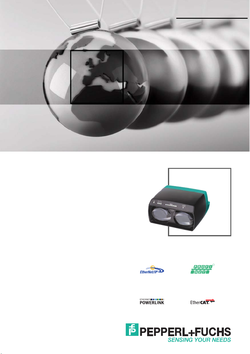
LS680-DA
Optical data coupler
FACTORY AUTOMATION
R
Page 2

LS680-DA
With regard to the supply of products, the current issue of the following document is applicable: The
General Terms of Delivery for Products and Services of the Electrical Industry, published by the
Central Association of the Electrical Industry (Zentralverband Elektrotechnik und Elektroindustrie
(ZVEI) e.V.) in its most recent version as well as the supplementary clause: "Expanded reservation
of proprietorship"
Page 3

LS680-DA
Contents
1 Introduction......................................................................... 4
1.1 Product documentation on the internet..........................................................4
2 Declaration of conformity .................................................. 6
3 Safety................................................................................... 7
3.1 Symbols relevant to safety ............................................................................7
3.2 Intended use .................................................................................................7
3.3 General safety instructions ............................................................................8
4 Product Description ......................................................... 11
4.1 LS680-DA - Use and application.................................................................11
4.2 Displays and controls..................................................................................12
4.3 Interfaces and connections.........................................................................13
4.4 Delivery package ........................................................................................14
4.5 Accessories ................................................................................................14
4.5.1 Mounting accessories ............................................................................14
4.5.2 Connecting cable ...................................................................................14
4.5.3 Network connecting cable......................................................................14
5 Installation......................................................................... 15
5.1 Preparation .................................................................................................15
5.2 Mounting.....................................................................................................15
5.3 Connection .................................................................................................16
5.4 Storage and transport .................................................................................17
6 Commissioning................................................................. 18
6.1 Adjustment..................................................................................................18
6.2 Topology .....................................................................................................21
7 Maintenance and Repair.................................................. 22
7.1 Maintenance...............................................................................................22
7.2 Repair.........................................................................................................22
8 Troubleshooting................................................................ 23
8.1 What to do in the event of an error ..............................................................23
9 Appendix ........................................................................... 24
9.1 Technical data.............................................................................................24
2014-05
3
Page 4

LS680-DA
Introduction
1Introduction
Congratulations
You have chosen a device manufactured by Pepperl+Fuchs. Pepperl+Fuchs
develops, produces and distributes electronic sensors and interface modules for
the market of automation technology on a worldwide scale.
Before you install this device and put it into operation, please read the operating
instructions thoroughly. The instructions and notes contained in this operating
manual will guide you step-by-step through the installation and commissioning to
ensure the trouble-free usage of this product. This is useful to you, because with
this you:
■ support the safe operation of the device
■ can utilize the device’s entire range of functions
■ reduce faulty operation and the associated errors
■ reduce costs from downtime and incidental repairs
■ increase the effectiveness and operating efficiency of your plant.
Store this operating manual somewhere safe in order to have it available for future
work on the device.
After opening the packaging, please ensure that the device is intact and that the
package is complete.
Symbols used
The following symbols are used in this manual:
Handling instructions
You will find handling instructions beside this symbol
Note!
This symbol brings important information to your attention.
Contact
If you have any questions about the device, its functions, or accessories, please
contact us at:
Pepperl+Fuchs GmbH
Lilienthalstraße 200
68307 Mannheim
Telephone: +49 621 776-4411
Fax: +49 621 776-274411
E-Mail: fa-info@pepperl-fuchs.com
2014-05
4
Page 5
LS680-DA
Introduction
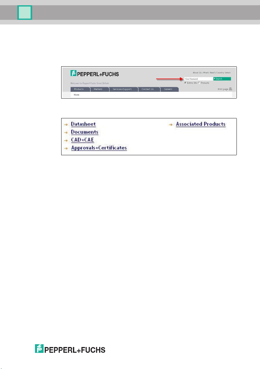
1.1 Product documentation on the internet
You can view all the relevant documentation and additional information on your
product at http://www.pepperl-fuchs.com. Simply enter the product name or
model number in the Product/Key word search box and click Search.
Select your product from the list of search results. Click on the information you
require in the product information list, e.g., Technical documents.
A list of all available documents is displayed.
2014-05
5
Page 6

LS680-DA
ISO9001
Declaration of conformity
2 Declaration of conformity
This product was developed and manufactured under observance of the
applicable European standards and guidelines.
Note!
A Declaration of Conformity can be requested from the manufacturer.
The product manufacturer, Pepperl+Fuchs GmbH, D-68307 Mannheim, has a
certified quality assurance system that conforms to ISO 9001.
6
2014-05
Page 7

LS680-DA
Safety
3Safety
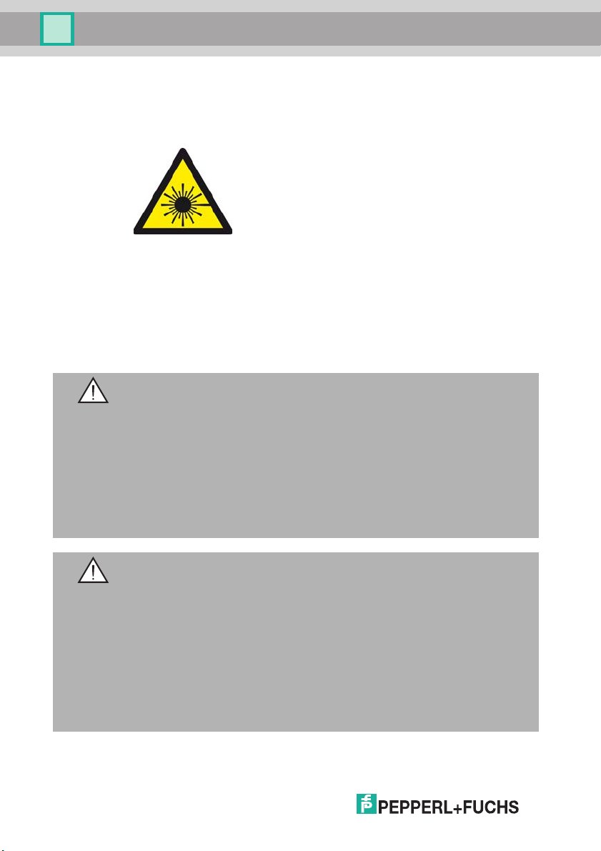
3.1 Symbols relevant to safety
Danger!
This symbol indicates an imminent danger.
Non-observance will result in personal injury or death.
Warn ing!
This symbol indicates a possible fault or danger.
Non-observance may cause personal injury or serious property damage.
Caution!
This symbol indicates a possible fault.
Non-observance could interrupt devices and any connected facilities or systems,
or result in their complete failure.
3.2 Intended use
The optical data coupler serves as an optical link between two Ethernet devices;
typically one is mobile.
Always operate the device as described in these instructions to ensure that the
device and connected systems function correctly. The protection of operating
personnel and plant is only guaranteed if the device is operated in accordance
with its intended use.
Only use recommended original accessories.
The operating company bears responsibility for observing locally applicable
safety regulations.
Installation and commissioning of all devices must be performed by a trained
professional only.
User modification and or repair are dangerous and will void the warranty and
exclude the manufacturer from any liability. If serious faults occur, stop using the
device. Secure the device against inadvertent operation. In the event of repairs,
return the device to your local Pepperl+Fuchs representative or sales office.
2014-05
7
Page 8
LS680-DA
Safety
3.3 General safety instructions
Class 1M laser product
This device is a class 1M laser product:
Standards
IEC 60825-1:2007 certified. Complies with 21 CFR 1040.10 and 1040.11 except
for deviations pursuant to Laser Notice No. 50, dated June 24, 2007.
Certifié cei 60825-1:2007. Conforme aux normes 21 CFR 1040.10 ET 1040.11 à
l'exception des écarts conformément à la notice du laser N° 50, Datée du
24 JUIN 2007.
LS680-DA-F2:
Warnin g!
Visible red class 1M laser light
The laser light can be a nuisance especially in a dark environment. Do not point at
people!
Do not observe with optical instruments such as magnifying glasses,
microscopes, telescopes or binoculars!
Install the device so that the warning is clearly visible and readable.
Maintenance and repairs should only be carried out by authorized service
personnel!
Warnin g!
Rayonnement laser visible produit laser classe 1M
L’irradiation peut entraîner des irritations dans un environnement sombre. Ne pas
orienter vers les personnes !
Ne pas regarder le rayon laser visible avec des instruments optiques comme les
loupes, microscopes, télescopes ou jumelles !
L’appareil doit être installé de manière à ce que les mises en garde soient
clairement visibles et lisibles.
L’entretien et les réparations doivent être réalisés exclusivement par le personnel
de service autorisé !
2014-05
8
Page 9

LS680-DA
Safety
LASER LIGHT
DO NOT VIEW DIRECTLY
WITH OPTICAL
INSTRUMENTS
LASER 1M LASER PRODUCT
IEC 60825-1: 2007 CERTIFIED.
COMPLIES WITH 21 CFR 1040.10
AND 1040.11 EXCEPT FOR DEVIATIONS PURSUANT TO LASER NOTICE
NO. 50, DATED JUNE 24, 2007
LUMIÈRE LASER
NE PAS REGARDER DIRECTEMENT
AVEC DES INSTRUMENTS OPTIQUES
PRODUIT LASER CLASSE 1M
CERTIFIÉ CEI 60825-1 : 2007.
CONFORME AUX NORMES 21 CFR
1040.10 ET 1040.11 À L’EXCEPTION
DES ÉCARTS CONFORMÉMENT
À LA NOTICE DU LASER
N° 50, DATÉE DU 24 JUIN 2007.
LS680-DA-F1:
Warn ing!
Infrared class 1M laser light
Do not observe with optical instruments such as magnifying glasses,
microscopes, telescopes or binoculars!
Install the device so that the warning is clearly visible and readable.
Maintenance and repairs should only be carried out by authorized service
personnel!
Warn ing!
Rayonnement laser invisible produit laser classe 1M
Ne pas regarder le rayon laser invisible avec des instruments optiques comme les
loupes, microscopes, télescopes ou jumelles !
L’appareil doit être installé de manière à ce que les mises en garde soient
clairement visibles et lisibles.
L’entretien et les réparations doivent être réalisés exclusivement par le personnel
de service autorisé !
INVISIBLE LASER RADIATION
INVISIBLE LASER RADIATION
DO NOT VIEW DIRECTLY
WITH OPTICAL
INSTRUMENTS
LASER 1M LASER PRODUCT
IEC 60825-1: 2007 CERTIFIED.
COMPLIES WITH 21 CFR 1040.10
AND 1040.11 EXCEPT FOR DEVIATIONS PURSUANT TO LASER NOTICE
NO. 50, DATED JUNE 24, 2007
RAYONNEMENT LASER IN VISIBLE
NE PAS REGARDER DIRECTEMENT
AVEC DES INSTRUMENTS OPTIQUES
PRODUIT LASER CLASSE 1M
CERTIFIÉ CEI 60825-1 : 2007.
CONFORME AUX NORMES 21 CFR
1040.10 ET 1040.11 À L’EXCEPTION
DES ÉCARTS CONFORMÉMENT
À LA NOTICE DU LASER
N° 50, DATÉE DU 24 JUIN 2007.
2014-05
9
Page 10

LS680-DA
Safety
Only use recommended original accessories.
The operating company bears responsibility for observing locally applicable
safety regulations.
Installation and commissioning of all devices must be performed by a trained
professional only.
User modification and or repair are dangerous and will void the warranty and
exclude the manufacturer from any liability. If serious faults occur, stop using the
device. Secure the device against inadvertent operation. In the event of repairs,
return the device to your local Pepperl+Fuchs representative or sales office.
Caution!
Controls or adjustments
Use of controls or adjustments or performance of procedures other than those
specified herein may result in hazardous radiation exposure
10
2014-05
Page 11

LS680-DA
Product Description
4 Product Description
4.1 LS680-DA - Use and application
The optical data coupler serves as an optical link between two Ethernet devices;
typically one is mobile. The opening angle is optimized for operations in high rack
storage.
With the optical data coupler, devices with industrial Ethernet topologies, such as
PROFINET, Ethernet/IP and other Ethernet protocols, can be connected. The
physical transfer takes place protocol-free with 100 MBit/s full duplex. The
connection to a number of modules must be implemented using switches that
have been certified for use with the bus system in question. All layer 2 telegrams
(IEEE 802.3 Clause 25) are physically transported. There is no saving of
telegrams, so the transfer is not delayed at all.
Modules operating at a data rate of 10 MBit/s can be connected using a switch.
Isochronous real-time systems can also be driven to a certain extent on account
of the variable light propagation time.
The LS680 uses semiconductor lasers as optical transmitters. The dilation of the
light beam and the use of return map blocks guarantee the harmlessness of the
devices in accordance with laser class 1M. The transmitting beam must not be
viewed with telescopes or binoculars from distances of less than 20 m. At longer
distances, the limit values for laser class 1 are not exceeded, even when viewed
through a telescope with a 50 mm aperture.
2014-05
11
Page 12

LS680-DA
PWR S I G N A L
LASER
ERROR
LAN
OPT
ERR
1 2 3 4 5 6
1
2
3
4
5
6
Product Description
4.2 Displays and controls
PWR
Lights up when the device is connected to the supply voltage.
ERR
Status of the overall connection. Lights up if the signal is not strong enough to establish a connection (if misaligned or if the light beam is obstructed) and also when there is a fault on the optical
channel, e.g., as a result of extraneous light. It must not illuminate under normal circumstances.
LAN
Status of the cable connection. The LAN LED (yellow) indicates a physical connection to the next
module on the cable. If it is not on, this indicates a connection problem. The LAN LED lights up permanently as long as no data is being transferred. Flashing of the LAN LED indicates the presence
of data packets on the LAN.
OPT
Status of the optical connection. The OPT LED flashes when the optical connection is stabilized
through correct alignment.
SIGNAL
Indicate the reception signal strength. Reaching the yellow area is sufficient to indicate error-free
reception. If the alignment is correct, two green LEDs should light up at the nominal det ection range.
To avoid excessive bus loading due to transmission errors, data transfer is blocked below the yellow area.
LASER ERROR
If the permitted internal temperature is exceeded, this LED will flash, although the transmission
power is not reduced. If an internal activation error such as overcurrent is detected, the laser is
switched off, and an attempt then made every second to resume normal operation. Meanwhile, the
LASER ERROR LED lights up for 30 secs ... 60 secs, even if the process was unique, e.g., as the
result of an EMC event.
12
2014-05
Page 13

LS680-DA
1
3
4
2
1
4
6
7
8
53
2
1
3
4
2
Product Description
4.3 Interfaces and connections
The device includes the following connections:
Power supply
There is an 4-pin M12 connector on the rear of the housing to connect the power
supply and the alarm output. The following diagram shows the pin assignment:
Figure 4.1 Power supply and alarm output connection layout
1 24 V power supply:
2 n.c.
3 Ground (GND)
4 Alarm
Service
The 8-pin M12 connector on the rear of the housing is for service purposes.
Network
There is a 4-pin D-coded M12 socket on the rear of the housing for connecting to
the Profinet or Ethernet/IP network. The following diagram shows the pin
assignment:
Figure 4.2 Network connection layout
1 Transmit Data (+)
2 Receive Data (+)
3 Transmit Data (-)
4 Receive Data (-)
2014-05
13
Page 14

LS680-DA
Product Description
4.4 Delivery package
■ LS680-DA
■ Leaflet
4.5 Accessories
4.5.1 Mounting accessories
The following mounting accessories are available.
Designation Description
OMH-LS610-01 Alignment/mounting aid
OMH-LS610-02 Direct mounting set (4 M4 threaded inserts)
Protective cap LS610
accessories
4.5.2 Connecting cable
The following female cordsets are available for selection:
Designation Description
V1-G-2M-PVC Female cordset, straight, M12, 4-pin, PVC cable, length: 2 m
V1-G-2M-PUR Female cordset, straight, M12, 4-pin, PUR cable, length: 2 m
V1-M-5M-PVC Female cordset, straight, M12, 4-pin, PVC cable, length: 5 m
V1-M-5M-PUR Female cordset, straight, M12, 4-pin, PUR cable, length: 5 m
V1-W-2M-PVC Female cordset, angled, M12, 4-pin, PVC cable, length: 2 m
V1-W-2M-PUR Female cordset, angled, M12, 4-pin, PUR cable, length: 2 m
V1-W-5M-PVC Female cordset, angled, M12, 4-pin, PVC cable, length: 5 m
V1-W-5M-PUR Female cordset, angled, M12, 4-pin, PUR cable, length: 5 m
Additional fastening for transport and storage.
A protective cap has already been placed onto the service
connector .
4.5.3 Network connecting cable
The sensor is connected to the network using an M12 connector.
Designation Description
V1SD-G-2M-PURABG-V45-G
V1SD-G-5M-PURABG-V45-G
V1SD-G-ABG-PG9 male connector, M12 D-coded, 4-pin for bus cable, field
14
Patch cable M12 to RJ45, length: 2 m
Patch cable M12 to RJ45, length: 5 m
attachable
2014-05
Page 15

LS680-DA
Installation
5 Installation
5.1 Preparation
Unpacking the unit
1. Check that all package contents are present and undamaged.
If anything is damaged, inform the shipper and contact the supplier.
2. Check that all items are present and correct based on your order and the
shipping documents.
If you have any questions, please contact Pepperl+Fuchs.
3. Keep the original packing material in case you need to store or ship the unit at
a later time.
5.2 Mounting
The device has two mounting holes as well as four retaining feet for easy
installation. M4 inserts can also be pressed into these four feet. This allows
existing adjustment and mounting options to be used. We also offer other
mounting accessories to facilitate fast mounting and adjustment. See chapter
4.5.1
The following illustration shows all the relevant device dimensions in mm:
Receiver
90
97.5
36
81
170
LAN
Socket M12 x 1, 4-pin
D-coded
Service
Connector M12 x 1, 8-pin
A-coded
Power
Socket M12 x 1, 4-pin
A-coded
2014-05
Output Laser, class 1M laser productAlignment aid
171
Earthing plate
15
Page 16

LS680-DA
Installation
Mounting on a P+F adjustment device
The mounting accessories (OMH-LS610-01) consist of a mounting bracket and
an integral alignment device (in x and y axes). The required beam direction (± 90°
rotation) can be set using the mounting accessories, which are fastened to the
mounting bracket using two M4 screws and the central M6 screw. The central
screw is for securing the unit in place following adjustment and should not be
tightened until the adjustment is finalized. To mount the optical data coupler,
squeeze the two front levers together and place feet into the four openings in the
adjustment device. The feet have to lock into place so that the levers can be
released outwards as far as the stop; if necessary the optical data coupler has to
be pressed down applying some force from the top to the center.
5.3 Connection
Connecting the power supply
The device conforms to protection class III. This means that the power has to be
supplied as a low protective voltage (PELV) and limited according to UL Class 2
(100 W). The power supply of the optical data coupler is a 18 V to 30 V DC. The
dielectric test voltage (shield against power/GND) is 50 V maximum.
To supply power to the sensor, proceed as follows:
1. Plug the 4-pin M12 mating cordset into the connector on the rear of the housing.
2. Screw the cap nut as far as it will go over the connector. This ensures that the
power cable cannot be inadvertently pulled out.
3. Now connect the supply voltage to the cable provided.
The sensor is now ready for operation.
16
2014-05
Page 17

LS680-DA
Installation
Grounding / Shielding
This type of grounding is not protective grounding, it acts solely as a down
conductor for cable-related faults and is not subject to any safety guidelines (e.g.
personnel protection). Functional grounding of the shields is required to provide
immunity to interference.
To ground the device, proceed as follows:
1. Make up a ground cable using a 6 mm flat connector with an adequate crosssection ( 1.5 mm²).
2. Plug the flat connector onto the pre-mounted insertion prong on the device.
3. Connect the other end of the ground cable to adjacent metal components
(e.g. mounting base, frame, etc.).
The device is now grounded.
Connecting the network
Both devices are connected to an M12 D-connector with the standard assignment
for PROFINET or Ethernet/IP. The LS680 automatically locates transmit and
receive lines (Auto-MDIX), so no crossover cable has to be used.
To connect the sensor to a network, proceed as follows:
1. Plug the 4-pin M12 mating cordset into the network connector on the rear of
the housing.
2. Screw the cap nut as far as it will go over the connector. This ensures that the
power cable cannot be inadvertently pulled out.
3. Now connect the network cable to the network connection provided for this
purpose.
The sensor is now ready for operation.
Note!
Data cables must conform CAT5. Do not use UTP (unshielded twisted pairs) for
reasons of electrical immunity.
5.4 Storage and transport
For storage and transport purposes, package the unit using shockproof
packaging material and protect it against moisture. The best method of protection
is to package the unit using the original packaging. Furthermore, ensure that the
ambient conditions are within allowable range.
2014-05
17
Page 18

LS680-DA
Commissioning
6 Commissioning
6.1 Adjustment
Alignment aid/ signal strength
An alignment LED, which can be seen from a long way off, is located on the front
panel as an alignment aid. As soon as a receiver detects the transmitter light of
the device opposite it, the flashing frequency of the alignment aid decreases. If
the light goes out, this indicates that the devices are optimally aligned and
sufficient signal strength is available. The bargraph display shows the receiving
level. The optical data coupler is designed to ensure that an adequate level of
received light is obtained over the entire transmitter. For technical reasons,
however, the maximum received light is often not in the center of the spot. To
ensure the best possible alignment, center the light spot horizontally and vertically
with the other optical data coupler device. The drop-off in intensity at the edge of
the spot is very pronounced, which makes the edges easy to locate.
SIGNAL
18
Signal-indicator red area yellow area green area
(at least one LED) (at least one LED)
State weak signal sufficient signal strength signal with function reserve
function reserve output active
Transmission blocked released transmission with
function reserve
Alignment-LED fast flashing slow flashing off
Figure 6.1 Explanation of display and operating state
In “high signal strength” mode (green zone), the received signal strength of the
optical data coupler is sufficient for operational purposes. The optical data coupler
should operate in the green zone within the nominal range (at least one green
LED); if the received strength drops below this limit level, the alarm output is deenergized. Telegrams continue to be sent until the received strength drops below
the level required for operational purposes (red LED only).
2014-05
Page 19

LS680-DA
Commissioning
Aligning using the adjustment alignment aid
The beam axis is aligned in the x and y direction using the two adjustment screws
(hollow, 5 mm). This position is then fixed by tightening the central screw. Ethernet
data communication is not needed for the alignment.
Alignment sequence
1. Place the adjustment alignment aid on the bracket in the required direction and
tighten the two M4 nuts. Screw in the M6 central screw, but do not tighten it yet.
2. Place the optical data coupler in the adjustment alignment aid. Connect the
power supply (Power).
3. Roughly align the device at a distance of around 3 - 5 m until both signal
indicators lie in the green zone. Ensure that the optical data couplers are at
the same height and are not offset.
4. Move both optical data couplers about 20 m apart and turn the adjustment
screws Y until the alignment LED starts to flash slowly. Now turn the same
screw in the opposite direction, counting the number of turns that the
alignment LED remains off before it starts flashing again. Finally, turn the
adjustment screw back (towards the middle) by half the number of turns.
Perform the same procedure in the x direction.
5. Increase the distance to maximum. Adjust the device further if necessary.
2014-05
19
Page 20

LS680-DA
F2
F1
F1
F2
a
d
Commissioning
6. We recommend to carry out the height adjustment before the lateral
Parallel light paths
If two transmission paths are installed next to each other without any optical
separation, then the optical data couplers must be installed opposite in pairs to
avoid cross-talk. A minimum distance ‘a’ between the beam axes is not required,
provided that the adjacent pairs have the identical overall distance ‘d.’
adjustment, as the height adjustment can mechanically modify the lateral
position, but not the other way round.
Once you have made the adjustments, tighten the central M6 screw to fix
the position in the horizontal direction.
Figure 6.2 Parallel light paths
In such arrangements, disconnecting one side of an optical data coupler is not
permitted. Similarly, the light beam must not be obstructed.
2014-05
20
Page 21

LS680-DA
VDM
100
F1 F2
Light spot of transmitter
Reflector
F1
F1 F1
F1
F2
F2
F2
F2
Switch
stationary
Vehicles
Commissioning
Parallel arrangement with VDM100 distance measurement sensors
The optical data coupler and distance measurement sensors of the type VDM100
can be arranged in parallel. A minimum distance of the units is not required.
6.2 Topology
The optical data coupler does not contain any address routing logic (switch). This
means that the distribution of the information must always be controlled by an
external switch. The internal Ethernet adapter is permanently set to 100 MBit full
duplex, as this is the only format that is converted for the optical transmission. Any
adjustments required to connection modes must be made using the external
switch. The pair of optical data couplers effectively replace a cable, the maximum
cable lengths always relate to the distance from the ODC to the appropriate
switch. The signal propagation time, on the other hand, depends on the physical
distance between the two ODCs; it amounts to 3.3 ns for each meter of light path.
Figure 6.3 Topology
2014-05
21
Page 22

LS680-DA
Maintenance and Repair
7 Maintenance and Repair
7.1 Maintenance
To get the best possible performance out of your device, keep the optical unit on
the device clean and clean it when necessary.
Observe the following instructions when cleaning:
■ Do not touch the optical unit with your fingers.
■ Do not immerse the device in water. Do not spray the device with water or
other fluids.
■ Do not use a scouring agent to clean the surface of the device.
■ Use a cotton or paper cloth moistened with water or isopropyl alcohol (not
soaked).
■ Remove any residual alcohol using a cotton or paper cloth moistened with
distilled water (not soaked).
■ Wipe the surface of the device dry using a lint-free cloth.
7.2 Repair
The devices must not be repaired, changed or manipulated. If there is a defect,
the product must always be replaced with an original device.
22
2014-05
Page 23

LS680-DA
Troubleshooting
8 Troubleshooting
8.1 What to do in the event of an error
Before requesting a service call, please check that the following actions have
been taken:
■ Test the equipment according to the following checklist.
■ Telephone assistance from the Service Center in order to isolate the
problem.
Checklist
Displays
Fault
No display off off off off The power supply is
No network
connection
No optical
communication
Bargraph not
responsive
despite precise
alignment
Bargraph full
scale and data
errors
on off Network cable not
on on off Receiving level too low,
on off on on Not an error; individual
on on on on Overload of the device Move the device in
Cause RemedyPWR ERR LAN OPT
switched off or there is a
wiring fault in the
distributor or control
cabinet.
connected or incorrectly
connected
transfer blocked
scaling deviation in the
highest green signal
strength
Check whether there is
a reason why it is
switched off (installation
or maintenance work
etc.). Switch the power
supply on if appropriate.
Check the wiring
carefully and repair any
wiring faults.
Check the connection to
the next node; is the
LAN LED also off on
this node?
Improve alignment or
incorrect pairing; F1+F2
required
none
horizontal or vertical
direction by about
40 mm relative to the
other device
■ If none of the above solves the problem, contact the Service Center. Have
the exact model number of the sensor ready if possible.
2014-05
23
Page 24

LS680-DA
Appendix
9 Appendix
9.1 Technical data
General specifications
Effective detection
range
Threshold detection
range
Light source laser diode
Light type device F1 modulated infrared light
Light type device F2 modulated visible red light
Laser nominal ratings
Note INVISIBLE LASER RADIATION , DO NOT VIEW DIRECTLY
Laser class 1M
Wave length device F1 785 nm
Wave length device F2 660 nm
Pulse length 8 ns
Repetition rate 62.5 MHz
Maximum optical power
output
Diameter of the light
spot
Angle of divergence 0.9 °
Ambient light limit > 10000 Lux
0 ... 150 m
180 m
WITH OPTICAL INSTRUMENTS
60 mW
1.5 m at a distance of 100 m
24
Functional safety related parameters
MTTF
d
Mission Time (TM) 10 a
Diagnostic Coverage
(DC)
58.6 a
0 %
Indicators/operating means
Data flow indicator LED green: OPTO-Link
Function indicator Signal strength (8 LED: Red, yellow, green)
LED yellow: LAN-Link
LED red: ERROR
2014-05
Page 25

LS680-DA
Appendix
Electrical specifications
Operating voltage 18 ... 30 V DC
No-load supply current 200 mA
Data rate 100 MBit/s (Fast Ethernet)
Interface
Interface type 100 BASE-TX
Output
Pre-fault indication
output
1 PNP, inactive when falling short of the stability control ,
short-circuit protected, max. 200 mA
Compliance with standards and directives
Directive conformity EMC Directive 2004/108/EC
Standard con formity
Sta nda rd s EN 61000-6-2 , EN 61000-6-4 , EN 60825-1
Approvals and certificates
UL approval cULus Listed
Ambient conditions
Ambient temperature -10 ... 50 °C (14 ... 122 °F)
Storage temperature -20 ... 70 °C (-4 ... 158 °F)
Mechanical specifications
Protection degree IP65
Connection 4-pin, M12x1 connector, standard (supply) ,
Material
Housing ABS / PC
Optical face plastic
Mass 700 g
2014-05
8-pin M12x1 connector, service ,
M12x1 socket, 4-pin, D-coded (LAN)
25
Page 26

Subject to modifications
Copyright PEPPERL+FUCHS • Printed in Germany
www.pepperl-fuchs.com
FACTORY AUTOMATION –
SENSING YOUR NEEDS
Worldwide Headquarters
Pepperl+Fuchs GmbH
68307 Mannheim · Germany
Tel. +49
621 776-0
E-mail: info@de.pepperl-fuchs.com
USA Headquarters
Pepperl+Fuchs Inc.
Twinsburg, Ohio
44087
·
USA
Tel. +1 330 4253555
E-mail: sales@us.pepperl-fuchs.com
Asia Pacific Headquarters
Pepperl+Fuchs Pte Ltd.
Company Registration
No. 199003130E
Singapore 139942
Tel. +65
67799091
E-mail: sales@sg.pepperl-fuchs.com
TDOCT2051E_ENG
05/2014
 Loading...