

Optical data coupler
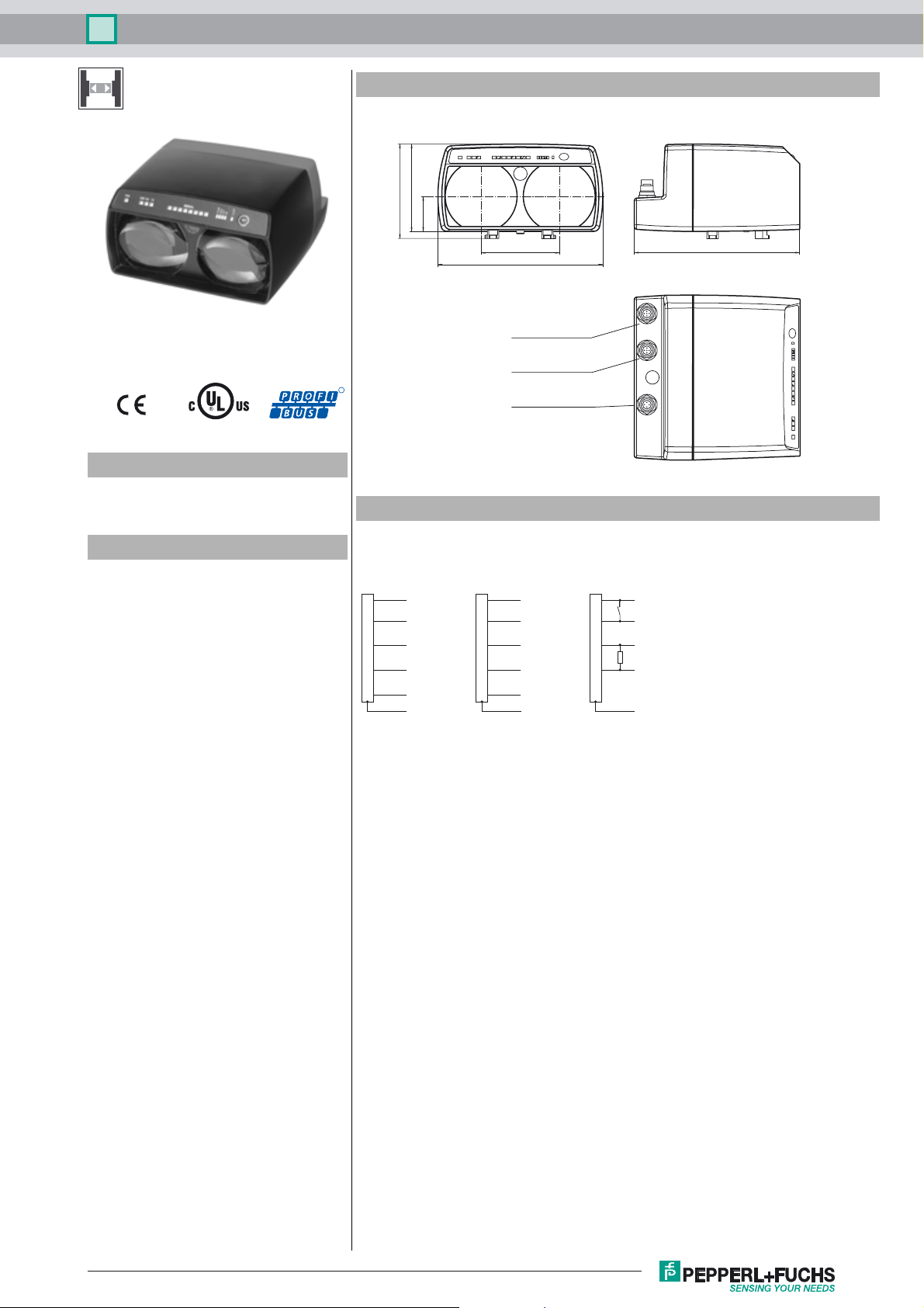
Dimensions
90
97.5
36
LS611-DA-P
Model Number
LS611-DA-P
Optical data coupler
Features
•Devices for PROFIBUS
• Identical units communicate with each
other
• Problem-free light beam interruption
due to TVT (Telegram Verification
Te c h n o l o g y )
• Plug connection for fast mounting
• Simple programming without opening
the device
• Usable up to detection range 0
• Line indicator for signal strength
81
170
Bus IN
Connector M12 x 1, 5-pin
B-coded
Bus OUT/Termination
Socket M12 x 1, 5-pin
R
B-coded
Power
Connector M12 x 1, 4-pin
Electrical connection
BUS OUT/TerminationBUS IN
n.c.
1
Rx/Tx-N (A)
2
n.c.
3
4
Rx/Tx-P (B)
5
Plug M12 x 1, 5-pin
B-coded
1)
According to the "PROFIBUS Mounting Recommendations", the connection of the screen with Pin 5 is not recommended.
If necessary, this type connection should be chosen if the contact of the screen cannot be established by screwing it to
the plug housing.
1)
Shield
Shield Shield
Socket M12 x 1, 5-pin
B-coded
VP
1
Rx/Tx-N (A)
2
DGND
3
4
Rx/Tx-P (B)
Shield
1)
5
Power
1
2
3
4
Plug M12 x 1, 4-pin
A-coded
24 V DC
Keylock
0 V DV
Alarm
n.c.
171
Release date: 2013-08-12 14:51 Date of issue: 2013-08-16 131631_eng.xml
Refer to “General Notes Relating to Pepperl+Fuchs Product Information”.
1
Optical data coupler
LS611-DA-P
Technical data
General specifications
Effective detection range 0 ... 150 m
Threshold detection range 200 m
Light source IRED
Light type modulated infrared light
Diameter of the light spot 2 m at a distance of 100 m
Angle of divergence 1.2 °
Ambient light limit > 10000 Lux
Functional safety related parameters
MTTFd 240 a
Mission Time (T
Diagnostic Coverage (DC) 0 %
Indicators/operating means
Data flow display LED green: emitter
Function display alignment aid: flashing front red LED Signal strength (8 LED:
Electrical specifications
Operating voltage UB18 ... 30 V DC
No-load supply current I
Data rate 93.75/187.5/500/1500 kBit/s , adjustable
Operation frequency 8.25 MHz
Interface
Interface type PROFIBUS DP-V0,-V1,-V2; FMS; MPI; FMS-DP mixed mode;
Input
Funct ion input Keyboard disabling, digital input (current sinking), closed ON
Output
Pre-fault indication output 1 PNP (switches if there is sufficient stability control) short-circuit
Ambient conditions
Ambient temperature -10 ... 50 °C (14 ... 122 °F)
Storage temperature -20 ... 70 °C (-4 ... 158 °F)
Mechanical specifications
Protection degree IP65
Connection 4-pin, M12x1 connector, standard (supply) ,
Material
Housing ABS / PC
Optical face plastic
Mass 700 g
Compliance with standards and directives
Standard conformity
Product standard EN 60947-5-2:2007
Sta nda rd s EN 61000-6-2
Approvals and certificates
UL approval cULus Listed
) 20 a
M
0
LED yellow: receiver LED red: faulty telegram
Red, yellow, green) Baud rate , C1CP (collision protection)
200 mA
galvanically isolated
protected, max. 200 mA
5-pin, M12x1 connector, B-coded (Bus In) ,
5-pin, M12x1 socket, B-coded (Bus Out/Termination)
Accessories
OMH-LS610-05
Mounting bracket for optical data coupler
and distance measurement devices
OMH-LS610-31
Mounting bracket for optical data coupler
and distance measurement devices
OMH-LS610-32
Mounting bracket for optical data coupler
and distance measurement devices
ICZ-TR-V15B
Terminal resistor for PROFIBUS
Schutzkappe LS610 Zubehoer
M12 protective cap set (connector + socket) for series LS610 / LS611
Funktionserdung LS610/VDM100 Zubehoer
Function grounding for LS610 / LS611 /
VDM100 series
V15B-G
Cable socket, M12, for PROFIBUS, adjustable
V15SB-G
Cable connector, M12, for PROFIBUS,
adjustable
OMH-LS610-01
Mounting bracket for optical data coupler
V15-G-PG9
Female connector, M12, 5-pin, field attachable
OMH-LS610-02
Direct mounting set consisting of 4 x M4
threaded inserts
OMH-LS610-03
Mounting bracket with deviation mirror for
optical data coupler
Other suitable accessories can be found at
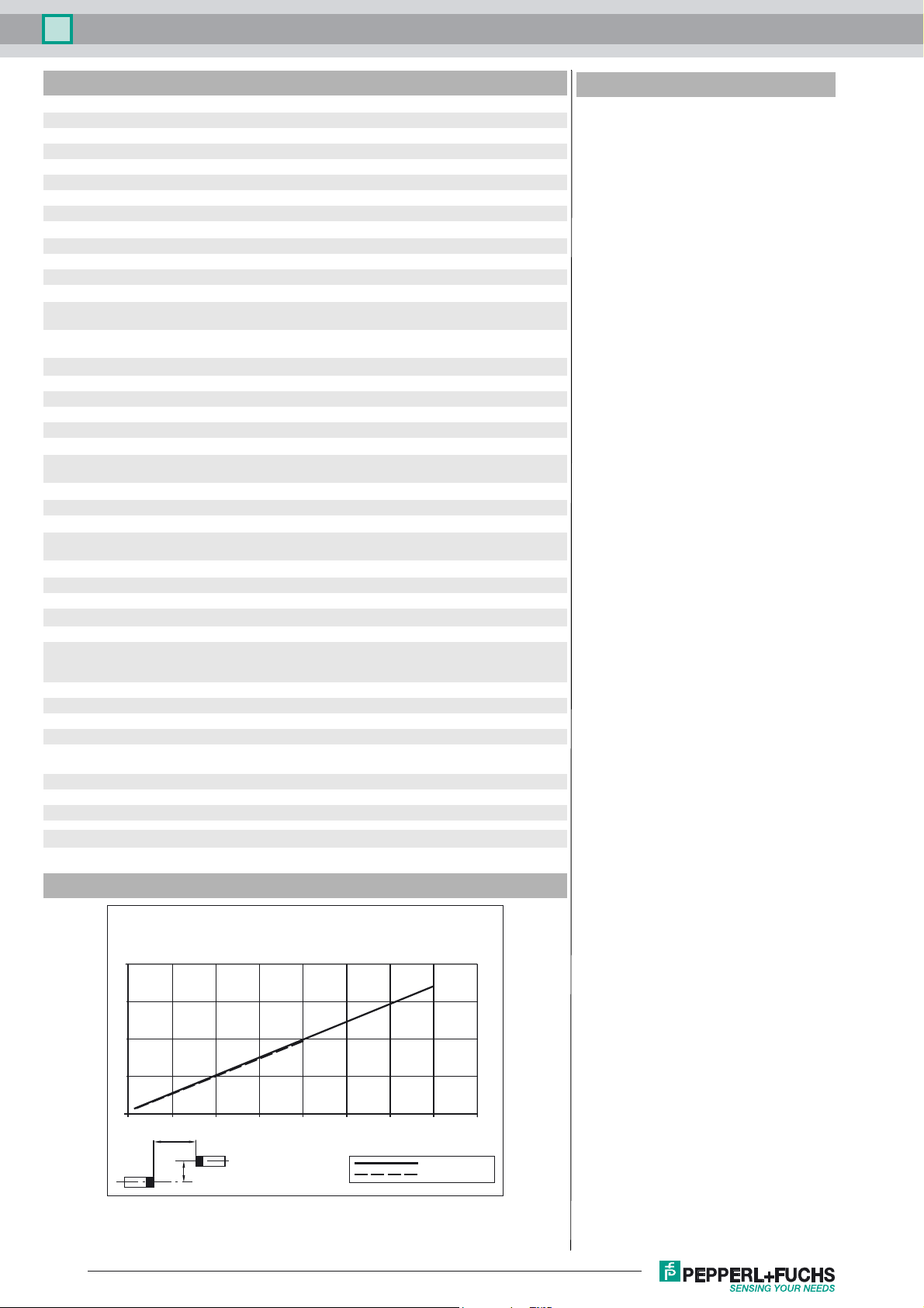
Curves/Diagrams
Characteristic response curve
Offset Y [m]
4
3
2
1
0
0 50 100 150 200 250 300 350 400
Refer to “General Notes Relating to Pepperl+Fuchs Product Information”.
x
y
2
LS 611-DA...
Distance X [m]
LS611-DA-.../35
LS611-DA-...
Release date: 2013-08-12 14:51 Date of issue: 2013-08-16 131631_eng.xml

Optical data coupler
LS611-DA-P
Relative received light strength
Stability control
100
10
1
0
50
100
x
150
200
250
300
LS 611-DA
400
350
Distance X [m]
LS611-DA-.../35
LS611-DA-...
Function
The LS611-DA-P is a device for serial data transfer in PROFIBUS systems with transfer rates up to 1500 kbit/s and ranges up
to 300 m. But the device can also be used without problem for data rates and operating ranges below these values. Two identical
LS611-DA-P devices are required to create the data transfer path.
Data transfer
The data are transfered in both directions by means of modulated infrared light. In this process the information at the input interface is modulated on the carrier signal in real time by means of Frequency Shift Keying (FSK). The appropriate demodulation
and output on the output interface takes place in the receiver.
Function displays/Stability control
A high-visibility alignment LED on the front of the device is provided to aid alignment. As soon as a receiver detects the light
emitted from the opposite device the flashing frequency of the alignment LED reduces. By going out, the same LED finally signals that the devices are optimally aligned with each other and that there is adequate stability control. For fine adjustment, the
optical data coupler is additionally provided with a bar graph display (Signal display), which provides a means of optimum adjustment.
State weak signal sufficient signal strength signal with function reserve
Transmission blocked released transmission with
function reserve
Alignment-LED fast flashing slow flashing off
Signal-indicator red area yellow area green area
(at least one LED)
Operation
The baudrate can be selected and modified by means of a push button. Operational readiness, data activity and fault signals
are indicated via LEDs. The push button can be inhibited to prevent manipulation and unintentional parameter changes via an
electrical signal.
Message processing.
In order to prevent the operation
of the connected bus from malfunction in the event of the interruption of the light beam, the
transfer of invalid messages is prevented. The signals are regenerated with bit and sign accuracy and sent to the bus with quartz
stability. This also provides the additional effect of optimum signal processing; the signal quality is electrically and timewise identical to that of the original PROFIBUS station.
Collision suppression
In systems with a number of light paths, in which there are active PROFIBUS stations ("Masters", e.g. operation panels) on the
moving side, a sequential fault can occur after a light path from a master has been broken, which leads to a collision with the
more important master of the master terminal station (Control), resulting in the considerable disruption of the data exchange on
the stationary side or even disruption of the data traffic with other light paths.
Release date: 2013-08-12 14:51 Date of issue: 2013-08-16 131631_eng.xml
Refer to “General Notes Relating to Pepperl+Fuchs Product Information”.
3

Optical data coupler
In order to avoid such a collision the function C1CP (Class 1 Master Collision Protection) can be brought into the circuit on the
stationary side. This prioritises the direction of transfer on this side after a light beam has become broken.
Mounting
Mounting takes place using an appropriate accessory, e.g. OMH-LS610-01 for wall mounting.
The x-y positioning is set prior to delivery. The device is secured in the desired beam direction (±90° rotation is possible) on the
support bracket.
LS611-DA-P
Refer to “General Notes Relating to Pepperl+Fuchs Product Information”.
4
Release date: 2013-08-12 14:51 Date of issue: 2013-08-16 131631_eng.xml
 Loading...