

Page 1
Optical data coupler
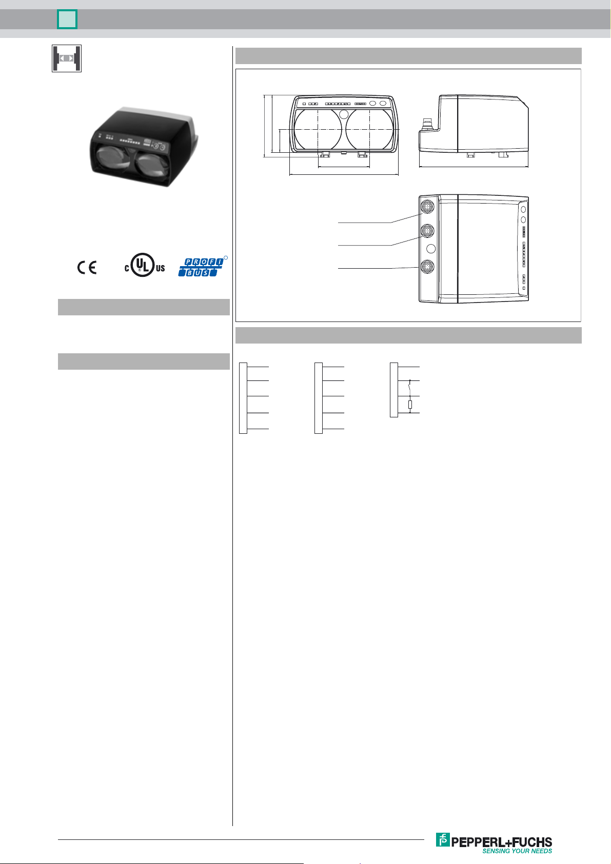
Dimensions
90
97.5
36
LS610-DA-P/F2/146
Model Number
LS610-DA-P/F2/146
Optical data coupler
Features
•Devices for PROFIBUS
• Version for low temperature applications
• Problem-free light beam interruption
due to TVT (Telegram Verification
Te c h n o l o g y )
• Plug connection for fast mounting
• Simple programming without opening
the device
• Usable up to detection range 0
• Line indicator for signal strength
R
Electrical connection
n.c.
1
Rx/Tx-N
2
n.c.
3
4
Rx/Tx-P
5
Shield Shield
Plug M12 x 1, 5-pin
B-coded
81
170
Bus IN
Connector M12 x 1, 5-pin
B-coded
Bus OUT/Termination
Socket M12 x 1, 5-pin
B-coded
Power
Connector M12 x 1, 4-pin
BUS OUT/TerminationBUS IN
VP
1
Rx/Tx-N
2
DGND
3
4
Rx/Tx-P
5
Socket M12 x 1, 5-pin
B-coded
Power
1
2
3
4
Plug M12 x 1, 4-pin
A-coded
171
+UB+UB
Keylock
0 V
Alarm
Release date: 2015-03-23 11:21 Date of issue: 2015-03-23 185148_eng.xml
Refer to “General Notes Relating to Pepperl+Fuchs Product Information”.
1
Page 2

Optical data coupler
LS610-DA-P/F2/146
Technical data
General specifications
Effective detection range 0 ... 120 m
Threshold detection range 140 m
Light type modulated infrared light
Diameter of the light spot 2 m at a distance of 100 m
Angle of divergence 1.1 °
Ambient light limit > 10000 Lux
Functional safety related parameters
MTTFd 250 a
Mission Time (TM) 20 a
Diagnostic Coverage (DC) 0 %
Indicators/operating means
Data flow indicator LED green: emitter
Function indicator alignment aid: flashing front red LED Signal strength (8 LED:
Control elements membrane keys, 2 keys, can be electrically locked
Electrical specifications
Operating voltage UB18 ... 30 V DC
No-load supply current I
Data rate 93.75; 187.5;(350); 500;1500 kBit/s , adjustable
Operation frequency F2 = 12.5 MHz
Interface
Interface type PROFIBUS, galvanically isolated
Input
Funct ion input Keylock, internal Pull-up resistor
Output
Pre-fault indication output 1 PNP (switches if there is sufficient stability control) short-circuit
Sta nd ard confor mi ty
Stan dar ds EN 60947-5-2 , CE , EN 61000-6-2
Ambient conditions
Ambient temperature -30 ... 50 °C (-22 ... 122 °F) , For use in dry cold
Storage temperature -30 ... 70 °C (-22 ... 158 °F)
Mechanical specifications
Degree of protection IP65
Connection 4-pin, M12x1 connector, standard (supply) ,
Material
Housing ABS / PC
Optical face plastic
Mass 700 g
Approvals and certificates
Approvals CE, cULus
LED yellow: receiver LED red: faulty telegram
Red, yellow, green) Baudrate, operating mode
200 mA
0
keypad locked with 0 V
protected, max. 200 mA
5-pin, M12x1 connector, B-coded (Bus In) ,
5-pin, M12x1 socket, B-coded (Bus Out/Termination)
Accessories
ICZ-TR-V15B
Terminal resistor for PROFIBUS
V15SB-G
Cable connector, M12, for PROFIBUS,
adjustable
V15B-G
Cable socket, M12, for PROFIBUS, adjustable
V15-G-PG9
Female connector, M12, 5-pin, field attachable
Funktionserdung LS610/VDM100 Zubehoer
Function grounding for LS610 / LS611 /
VDM100 series
Schutzkappe LS610 Zubehoer
M12 protective cap set (connector + socket) for series LS610 / LS611
OMH-LS610-01
Mounting bracket for optical data coupler
OMH-LS610-02
Direct mounting set consisting of 4 x M4
threaded inserts
OMH-LS610-03
Mounting bracket with deviation mirror for
optical data coupler
OMH-LS610-05
Mounting bracket for optical data coupler
and distance measurement devices
OMH-LS610-31
Mounting bracket for optical data coupler
and distance measurement devices
OMH-LS610-32
Mounting bracket for optical data coupler
and distance measurement devices
Curves/Diagrams
Characteristic response curve
Offset Y [mm]
1400
1200
1000
800
600
400
200
0
0 20 40 60 80 100 120
x
y
Function
Refer to “General Notes Relating to Pepperl+Fuchs Product Information”.
2
LS 610-DA...
Distance X [m]
Release date: 2015-03-23 11:21 Date of issue: 2015-03-23 185148_eng.xml
Page 3

Optical data coupler
LS610-DA-P/F2/146
The LS610-DA-P is a device for serial data transmission in PROFIBUS-Systems at transmission rates up to 1500 kbit/s and a
distance range covering up to 240 m. Of cause the device can be employed at transmission rates and distance below these
values without any problems. A data transmission path consists of two devices LS 610-DA-P, one working at centre frequency
F1 and one working at centre frequency F2.
Data transmission
The data transmission is carried out by means of modulated infrared light in both directions. In the Emitter, the input interface
information is modulated onto the carrier signal by frequency shift keying (FSK) in real time. In the receiver the incoming optical
signal is de-modulated and made available at the output interface.
Function indicators/Function reserve
As adjustment aid, the device is equipped with a alignment LED, which can be observed over a long distance. As soon as a
receiver detects an incoming optical signal from the opposite device, the alignment LED’s flashing frequency slows down. Going
out indicates a good alignment and sufficient function reserve. For fine adjustment the device is equipped additional with a bar
graph-Indicator (signal-indicator), which makes an optimal alignment possible.
ENTER
PWRPWR ERR RX TX SIGNALSIGNAL
State weak signal sufficient signal strength signal with function reserve
Transmission blocked released transmission with
function reserve
Alignment-LED fast flashing slow flashing off
Signal-indicator red area yellow area green area
(at least one LED)
500 kBd
1,5 MBd
375 kBd
187 kBd
93 kBd
PROFIBUS
Connection between indicator and device status
If the bus is active, a yellow LED „RX“ (receive data) and a green LED „TX“ (transmit data) light up.
Operating
Due to two membrane keys, parameters like transfer rate and telegram verification can be selected and modified. The visualization of ready status, data transfer and error message is carried out via LEDs. to avoid manipulation or inadvertently parameter
change the keys can be electrically locked.
Telegram processing
To avoid bus error, caused by light beam interruption, Telegram Verification Technology (TVT) is implemented in this device.
The TVT prevents from transfers of invalid telegrams. The data get recovered bit by bit and word-fairly and are applied to the
bus quartz-stabilized. Thus an optimal signal conditioning is performed. The signals are electrically identical and simultaneous
to the original PROFIBUS clients signals.
The TVT can be de-activated. Due to this, the data transfer is mostly protocol free and the device is suitable for transferring
RS485 protocols, which have different timing conditions to the PROFIBUS.
Bus termination
If the data coupler is located at the end of a bus topology, a bus termination is required. An external standard termination resistor
(refer accessories) has to be connected to the M12 connector „Bus OUT/Termination“.
Installation
The mounting is carried out by using the suitable mounting accessory e. g. OMH-LS610-01 for wall mounting.
The x-y-adjustable carrier is delivered pre-assembled.It can be mounted in the desired direction (±90° rotation is possible) It
may be tightened not before mounting onto the mounting bracket by means of 2 M4-screws and the central M6-screw. The final
fixation after alignment is carried out by means of the central screw.
The data coupler can be snapped onto the alignment fixture, when the both spring forced handles at the front end of the fixture
are pressed together. After snap in, the handles must be released for a reliable fixation of the device.
By means of the two adjustment screws (female hexagon 5 mm) the beam axis can be aligned in X- and Y-direction. Finally the
alignment gets fixed by tightening the central screw.
Release date: 2015-03-23 11:21 Date of issue: 2015-03-23 185148_eng.xml
Refer to “General Notes Relating to Pepperl+Fuchs Product Information”.
3
 Loading...