

Optical data coupler
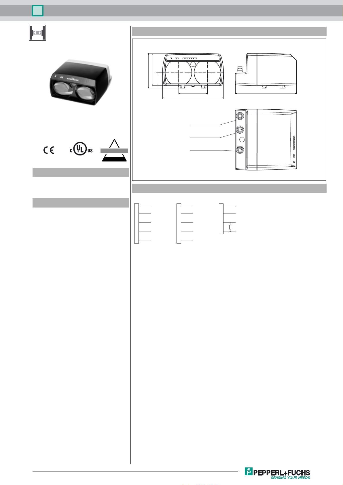
Dimensions
90
97,5
36
LS610-DA-IBS/F1
I
NTERBUS
Model Number
LS610-DA-IBS/F1
Optical data coupler
Features
•Devices for INTERBUS
• Plug connection for fast mounting
• No parameterization
• Usable up to detection range 0
• Line indicator for signal strength
Electrical connection
1
2
3
4
5
Plug M12 x 1, 5-pin
B-coded
DO
/DO
DI
/DI
GND GND
1
2
3
4
5
Socket M12 x 1, 5-pin
B-coded
81
170
Remote Bus IN
Connector M12 x 1, 5-pin
B-coded
Remote Bus OUT
Socket M12 x 1, 5-pin
B-coded
Power
Connector M12 x 1, 4-pin
DO
/DO
DI
/DI
PowerRemote Bus OUTRemote Bus IN
1
2
3
4
Plug M12 x 1, 4-pin
A-coded
171
+UB+UB
n.c.
0 V
Alarm
Release date: 2013-08-21 13:02 Date of issue: 2013-08-21 131634_eng.xml
Refer to “General Notes Relating to Pepperl+Fuchs Product Information”.
1
Optical data coupler
LS610-DA-IBS/F1
Technical data
General specifications
Effective detection range 0 ... 120 m
Threshold detection range 140 m
Light type modulated infrared light
Approvals CE, cULus
Diameter of the light spot 2 m at a distance of 100 m
Angle of divergence 1.1 °
Ambient light limit > 10000 Lux
Functional safety related parameters
MTTFd 260 a
Mission Time (T
Diagnostic Coverage (DC) 0 %
Indicators/operating means
Data flow display LED green: emitter
Function display alignment aid: flashing front red LED Signal strength (8 LED:
Electrical specifications
Operating voltage UB18 ... 30 V DC
No-load supply current I
Data rate 0 ... 2 MBit/s
Operation frequency F1 = 8.25 MHz
Interface
Interface type RS 422 , galvanically isolated
Output
Pre-fault indication output 1 PNP (switches if there is sufficient stability control) short-circuit
Sta nd ard confor mi ty
Stan dar ds EN 60947-5-2 , CE , EN 61000-6-2
Ambient conditions
Ambient temperature -10 ... 50 °C (14 ... 122 °F)
Storage temperature -20 ... 70 °C (-4 ... 158 °F)
Mechanical specifications
Protection degree IP65
Connection 4-pin, M12x1 connector, standard (supply) ,
Material
Housing ABS / PC
Optical face plastic
Mass 700 g
) 20 a
M
0
LED yellow: receiver
Red, yellow, green)
200 mA
protected, max. 200 mA
5-pin, M12x1 connector, B-coded (Remote Bus In) ,
5-pin, M12x1 socket, B-coded (Remote Bus Out)
Curves/Diagrams
Accessories
V15SB-G
Cable connector, M12, for PROFIBUS,
adjustable
V15B-G
Cable socket, M12, for PROFIBUS, adjustable
V15-G-PG9
Female connector, M12, 5-pin, field attachable
Funktionserdung LS610/VDM100 Zubehoer
Function grounding for LS610 / LS611 /
VDM100 series
Schutzkappe LS610 Zubehoer
M12 protective cap set (connector + socket) for series LS610 / LS611
OMH-LS610-01
Mounting bracket for optical data coupler
OMH-LS610-02
Direct mounting set consisting of 4 x M4
threaded inserts
OMH-LS610-03
Mounting bracket with deviation mirror for
optical data coupler
OMH-LS610-05
Mounting bracket for optical data coupler
and distance measurement devices
OMH-LS610-31
Mounting bracket for optical data coupler
and distance measurement devices
OMH-LS610-32
Mounting bracket for optical data coupler
and distance measurement devices
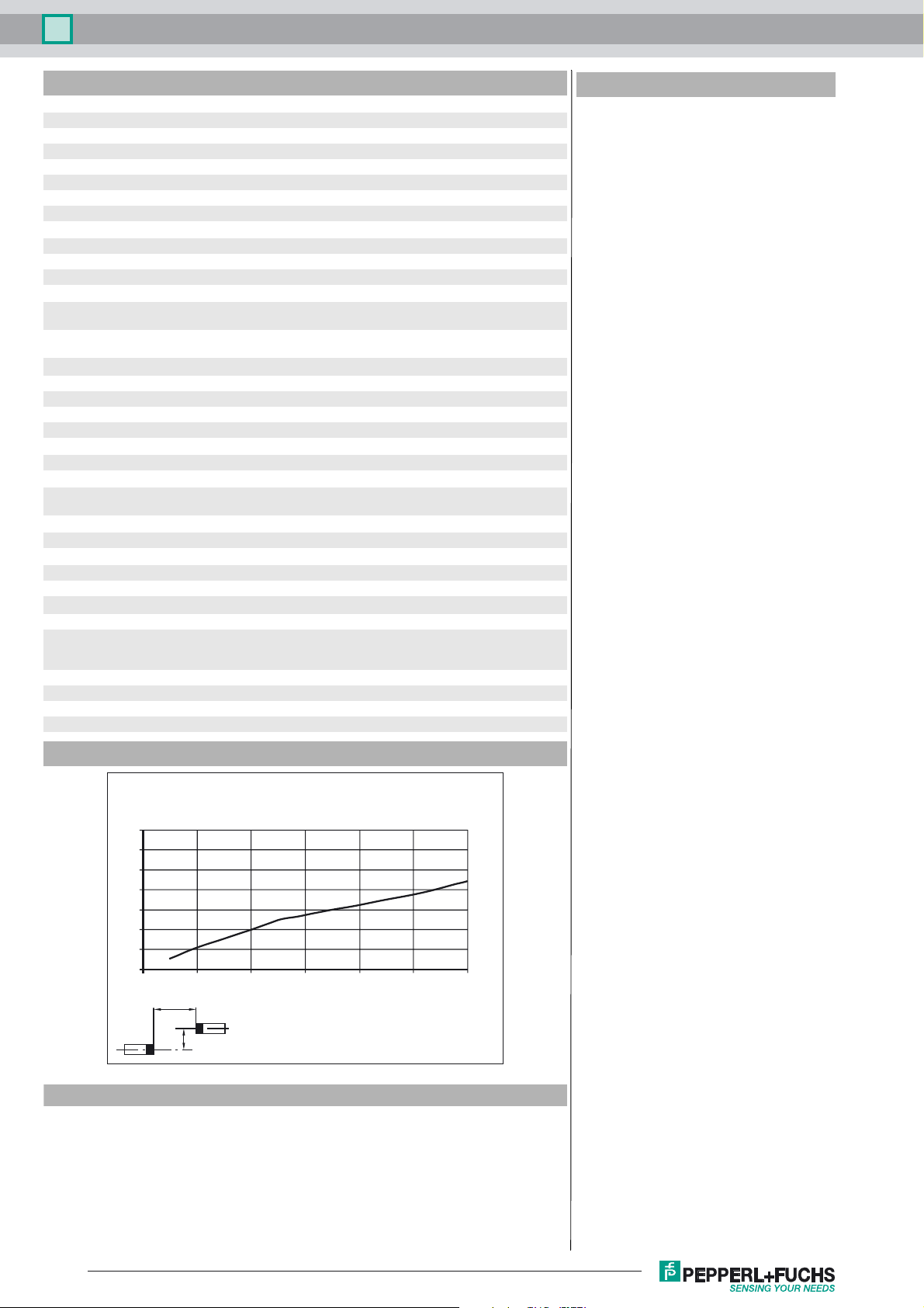
Characteristic response curve
Offset Y [mm]
1400
1200
1000
800
600
400
200
0
0 20 40 60 80 100 120
x
y
LS 610-DA...
Distance X [m]
Function
The LS610-DA-IBS is a device for serial data transmission in INTERBUS systems
with transmision rates of up to 2 MBit/sec and ranges up to 240 m. For data rates
and operating ranges lower than these values, the device can also be used with no
problems.
Refer to “General Notes Relating to Pepperl+Fuchs Product Information”.
2
Release date: 2013-08-21 13:02 Date of issue: 2013-08-21 131634_eng.xml
Optical data coupler
LS610-DA-IBS/F1
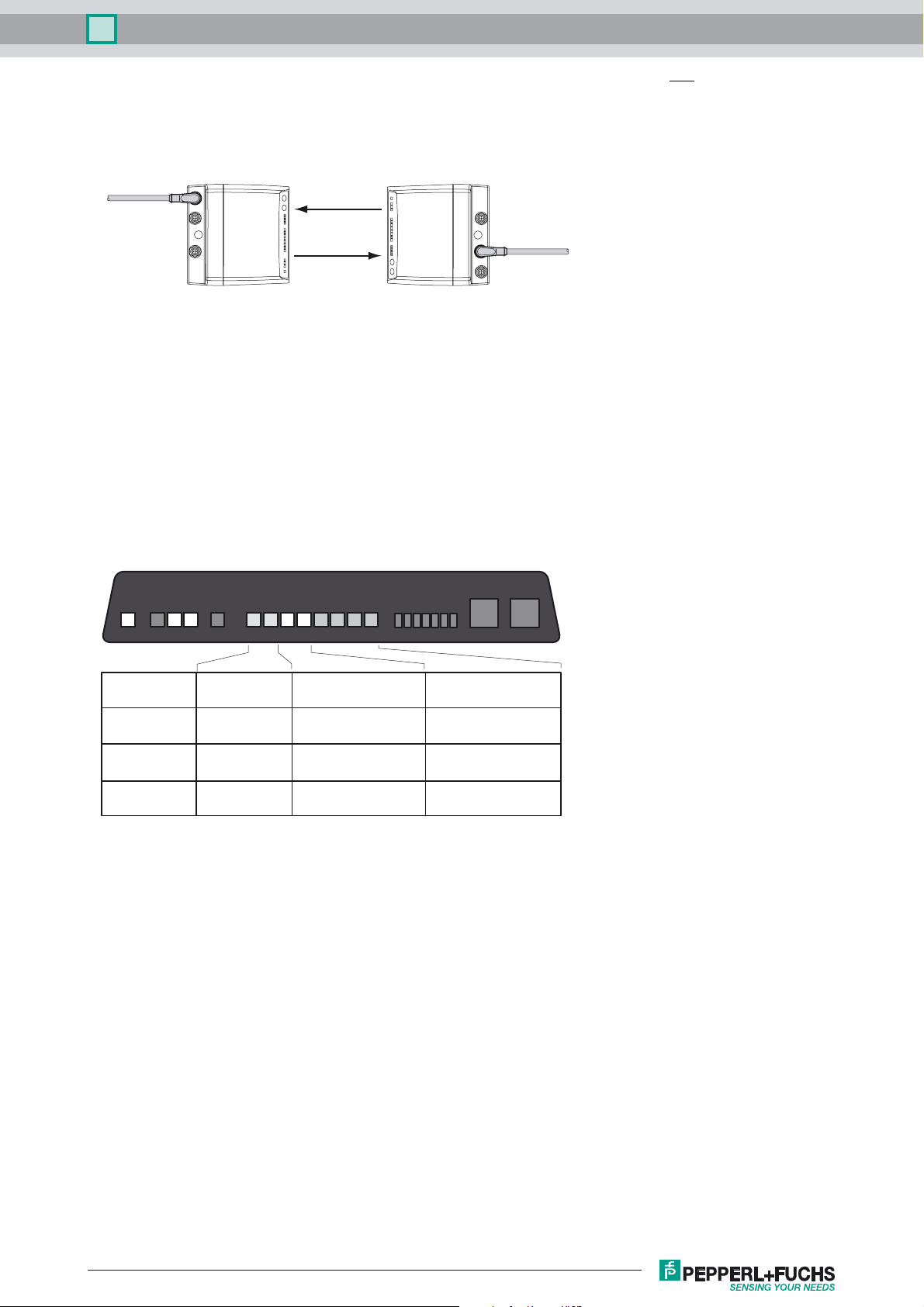
For one data transmission connection, an LS 610-DA-IBS unit with a mean frequency of F1 and an LS 610-DA-IBS unit with
mean frequency F2 are required.
The LS610-DA-IBS is intended for the direct connection of Interbus S units ("extension of bus cables"). It contains no bus connection logic, and is thus not suited for spur line installations. For this reason, only one of the M12 connectors should be used
at a time.
Bus incoming
Bus outgoing
F2 or F1F1 or F2
Data transmission
Data is transmitted in both directions using modulated infrared light. The information carried on the incoming bus is modulated
on the carrier signal in real time using frequency shift keying (FSK). In the reciever, the corresponding demodulation is performed and the data is output on the outgoing bus. The complete transmission process is performed using no protocols.
The LS610 DA-IBS includes level-type regeneration as well as complete voltage isolation of the data transmission circuits from
the power supply.
Function displays/function reserves
For alignment, there is an alignment LED on the unit's face which is visible from a distance. As soon as a receiver detects the
transmission light of the opposite unit, the blink frequency of the alignment aid is lowered. When it is extinguished, this signals
that the units are optimally aligned with one another, and enough functional reserve is available. For fine adjustment, the data
system is equipped with a bar graph display (signal display) which enables optimal alignment.
PWRPWR RX TX SIGNAL
State weak signal sufficient signal strength signal with
function reserve
Transmission blocked released transmission with
function reserve
Alignment-LED fast flashing slow flashing off
Signal-indicator red area yellow area green area
(at least one LED)
Connection between display and operational status
If the bus is active, a yellow LED "RX" is lit for received data and a green LED "TX" for transmitted data.
Installation
Installation is done with the corresponding accessories, for instance, OMH-LS610-01 for wall mounting.
The x/y adjustment is premounted at the factory. It is fastened to the mounting bracket in the desired transmission direction
(±90° rotation possible) with the two M4 screws and a central M6 screw. The middle screw is for fastening after adjustment and
should only be tightened afterwards.
The data photo sensor is inserted into the notches of the adjustment device while holding both of the front bolts together with
holding tabs. After insertion, the bolts are released and hold the unit securely by springing back.
Using the two adjustment screws (Inbus 5mm), the transmission axis can now be directed in the X and Y directions, and the
adjustment fixed in place by tightening the middle screw.
Release date: 2013-08-21 13:02 Date of issue: 2013-08-21 131634_eng.xml
Refer to “General Notes Relating to Pepperl+Fuchs Product Information”.
3
 Loading...