

Page 1
MANUAL
LGS Series
Switching Automation Light Grid
FACTORY AUTOMATION
Page 2

LGS Series
With regar d to the supply of products, the curre nt issue of the following documen t is applicable: The
General Terms of Delivery for Products a nd Se rvic es of the Electrical Indust ry, p ublished by the
Central Association of the Ele ctrica l Industry (Zentralve rband Elektrotechnik und Elektroindustrie
(ZVEI) e.V.) in its most recent version as well as the supplementary clause: "Expanded rese rvation
of proprietorship"
Page 3

LGS Series
Contents
1 Introduction......................................................................... 5
2 Declaration of Conformity ................................................. 6
2.1 Declaration of Conformity ..................................... ............... .........................6
3 Safety................................................................................... 7
3.1 Symbols Relevant to Safety ............... ................................................. .......... 7
3.2 Intended Use ............ ................................................. ............... ....................7
4 Product Description ........................................................... 9
4.1 Use and Applicat ion ..................................... .............. ...................................9
4.2 Indicato rs and Operating Elements ......................................................... ......9
4.3 Interfaces and Connections .......... .............................................................. 11
4.4 Accessories ................... ............... ................................................. ............. 12
4.5 Scope of Delivery ........... ................................................. ............... .............12
5 Installation ........................................................................ 13
5.1 Preparation . .............. ................................................. ............... ..................13
5.2 Mou ntin g ..... .............. ................................................. ............... ..................13
5.3 Multiple Positions ................................................................. ............... ........16
5.4 Connecting the Senso r Rails........................ .............. .................................17
5.5 Storage and Transportation .................................................. ............... ........20
6 Commissioning................................................................. 21
6.1 Final Ass embly ......... ............... ................................................. .............. ....21
6.2 Commis sioning the Light Grid......................................... ............... .............21
7 Operation........................................................................... 22
7.1 Operating the Light Gri d . ................................................. ............... .............2 2
7.1.1 Object Detection (Overhang Control) .......... ............... ............................27
7.1.2 Monitoring the Object Height with Height Controls .................... .............28
7.1.3 Object Identification ............. ................................................. .............. ....29
7.2 Commis sioning and Operating the Light Grid with IO-L ink ..........................30
8 Maintenance and Repair.................................................. 32
8.1 Mainten ance ........................................... .............. ......................................32
8.2 Repair ....................... ............... ................................................. .............. ....32
9 Troubleshooting................................................................33
9.1 Troubleshooting ............................ ............... ............................................... 33
239596 2019-09
3
Page 4

LGS Series
Contents
10 Appendix........................................................................... 35
10.1 Technical Data ............ ............... ............... ................................................ . 35
10.2 Type Code .......................................................... ............... ......................... 37
10.3 Response Times and Numb er of Beams .................................................... 38
10.4 Profile Length and Weight ..... ............... ................................................. ..... 41
10.5 Accessorie s ............................... ............... ................................................ . 4 2
10.5.1 Installation Accessories .................................................................... ..... 42
10.5.2 Co nnecting Cables ........... ............... ................................................. ..... 46
10.5.3 Accessories for IO -Link Operation ........................... ............... ............... 46
10.6 Parameterizing the Lig ht Grid ..... ............................................................... . 47
239596 2019-09
4
Page 5

LGS Series
Introduction
1 Introduction
Congratulations
You have chosen a devic e manufactured by Pepp erl+Fuchs. Pepper l+Fuchs
develops, produces and dist ribu tes electronic se nsors and interface modu les for
the market of automation techn ology on a worldwide sca le.
Before you install this device and p ut it into operation, please read the operating
instructions thoroug hly. The instructions and notes contained in this operat ing
man ual will guide you step-by-st ep throug h the installation and commissioning
procedures to ensure troub le-free use of this product. By doing so, you:
■
guarantee safe operation of the device
■
can utilize the entire ran ge of device functions
■
avoid faulty operation and associated errors
■
reduce costs from downtimes and incidental repairs
■
increase the e ffectiveness and ope rating efficiency of your plant.
Store this op erating manual somewhere safe in order to have it available for future
work on the device.
Directly after opening the packaging, please ensure that the device is intact and
that the p acka ge is c omplete.
Contact
If you have any questions about the device, its functions, or a ccess ories, pleas e
contact u s at:
Pepperl+Fuchs Gm bH
Lilienthalstraße 200
68307 Mannheim, Germany
Telephone: +49 (0)621 7 76-1111
Fax: +49 ( 0)621 776-271 111
Email: fa-info@de.pepperl-fuchs.com
Sym bols use d
The following symbols are used in this manual:
Note
This symbol draws your attention to important information.
Handling instructions
You will find hand ling instructions bes ide this symbol
239596 2019-09
5
Page 6

LGS Series
ISO9001
Declaration of Confo rmity
2 Declaration of Conformity
2.1 Declaration of Conformity
This product was d eveloped and ma nufactured unde r observan ce o f the
applica ble E uropean standards and guidelines.
Note
A Declaration of Conformity can be requested from the man ufacturer.
The product manufacturer, Pepper l+Fuchs GmbH, D-68 307 Mannheim, has a
certified quality a ssur ance system that con forms to ISO 9001.
6
239596 2019-09
Page 7
LGS Series
Safety
3 Safety
3.1 Symbols Relevant to Safety
Danger!
This symbol ind icates an imminent danger.
Non-observance will result in pers onal injury or death.
Warning!
This symbol ind icates a possible fau lt or danger.
Non-observance m ay cau se p ersonal injury or serious prope rty damage.
Caution!
This symbol ind icates a possible fau lt.
Non-observance co uld interrupt the dev ice and any conne cted systems and
plants, or result in their complete failure.
3.2 Intended Use
The LGS autom ation light grid is a comp act optical light grid that consists of a
emitter strip and a receiver strip. The detection field to be m onitored is located
between the emitte r strip and the receiver strip. The electronics for level
mea surement are located in the receiver strip.
Area s of Use
■
Object detection in the packaging and material hand ling secto rs
■
Detecting and counting irre gular objects
■
Measuring an d sorting objects of differen t heights (height co ntrol)
■
Presence and overhang cont rol in material handling systems
■
Overha ng control of load heights in tran spo rt systems a nd mater ial
handling applica tions
■
Web sag m onitorin g
■
Position or shape m onitoring
■
Gap detection
Caution!
Not a safety co mponent
The light grid is not a certified safety ligh t grid in accordance with EN 61496. It is
also not a safety com ponent under the terms of the EU Machiner y
Directive 2006 /42/EC. The ligh t grid must therefore not be used for the purpose o f
preventing r isk to individuals or parts of the bo dy.
Always operat e the device as desc ribed in th ese instructions to ensure that the
device and conn ected systems function correctly. The protection of operating
personnel and plant is only guaranteed if the device is operated in acco rdance
with its intended use.
239596 2019-09
7
Page 8

LGS Series
Safety
The device and its inp ut and output circuits must be operated from a power supp ly
that fulfills the req uirem ents of PELV/SELV systems.
Only use recommende d original accessor ies.
The operating com pany bears resp ons ibility for observing locally app licable
safety regulations.
Installation and commissioning of all devices may only be performed by trained
and qualified per sonnel.
User modification and or repair are dangerous and will void the warranty and
exclude the ma nufacturer from any liability. If serious faults occur, stop using the
device. Secure the device against inadverten t operation. In the event of repairs,
return the device to your local Pepper l+Fuchs representative o r sa les office.
239596 2019-09
8
Page 9

LGS Series
Product De scription
4 Product Description
4.1 Use and Application
LGS series: Tou ch it, save it—i ntelligent automation light grid with extras
Features
■
Adjustable b eam crossover for refining the resolution. The beam crossover
does no t alter the resp onse time
■
Optical synchronization o f both outer beams possible
■
Three separate o utputs for height control
■
Light-o n or dark- on op tions
■
Parameterizable object detection
■
Parameterizable bea m suppres sion (blanking )
■
Operation via touch field or extern al inp ut
■
IO-Link interface for ser vic e and process d ata, and for parameterization
Desc ript ion
In ad dition to the usual s tandard functions, LGS series light grids feature a range
of u seful extra functions previously found only in much more expensive dev ice
classes. These functions include ultra-quick ob ject detection even with beam
crossover, the option of identifying objects, and remote c ommunication via an IOLink interface. The blanking fun ction can be used to deactivate two connected
beam areas if unfavorable installation c onditions result in plant c omponents
exten ding into and interrupting the det ection field. The standby operating mode is
another feature for applications where light grids are n ot in con tinuou s op eration.
The LGS is modular in d esign and available with five different beam gaps (8 mm,
17 mm, 25 m m, 5 0 mm, and 100 mm) and detection field heights ranging from
100 mm to 3200 mm to enable extensive monitoring of the evalua tion a rea.
Integrated signa l evaluation means it is no t ne cessary to mo unt a sep arate
add itional switching device. The slimline profiles c an ea sily be mounted us ing
existing holes, the rear continuous groove, or the fixture s availab le as
accessories, enabling light grids in the LGS series to be used to maximum effect
and t ailored to the specific ap plication.
The switching light grid has one swit ching output, which displays an identified
object, and three height control outputs.
The LGS receiver strip also has an IO-Lin k interface, enabling advanced
parameter ization, extens ive configuration, identification, and diagnos is of the light
grid. This requires operation on an IO-Link master.
The SC (stability control) diagnostic output indicates an insufficient functional
reserve, e.g., due to misalignment or soiling. The receiver strip can be taught in for
various objects via a teach-in input. The touch b utton can also be replicated
externally via this input.
239596 2019-09
9
Page 10
LGS Series
2
3
2
3
Q
H1H2H3 F
2
Product De scription
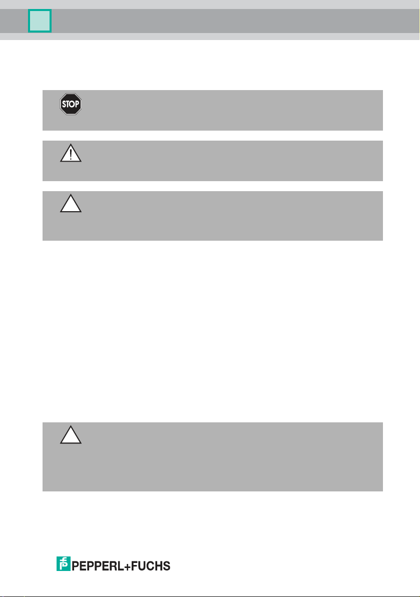
4.2 Indicators and Operating Elements
Emitter strip
Figure 4.1 Function indicator on the emitter strip
2 O perating indicator : Indicates power on or power save mode
3 S tatus indicator: Indicates transmi ssion power, fault state, or activ e test input
Receive r strip
Figure 4.2 Function indicator on the receiver strip
2 O perating indicator : Indicates power on, power save mode, active IO-Link, or fault state
3 S tatus indicator: Indicates detectio n field status, functional rese rve, or fault s tate
10
On the receiver strip be hind the plastic front panel the re are 12 illuminated
pictograms. The pictogra ms indicate the functional state and allow you to
parame terize the system. The two outer pictograms indicate the position of th e
two oper ating buttons (capacitive touch buttons) for pa ramet erization.
239596 2019-09
Page 11
LGS Series
7
6
5
4
2
1
11
10
9
8
12
3
Q
H1
H2
H3 F
2
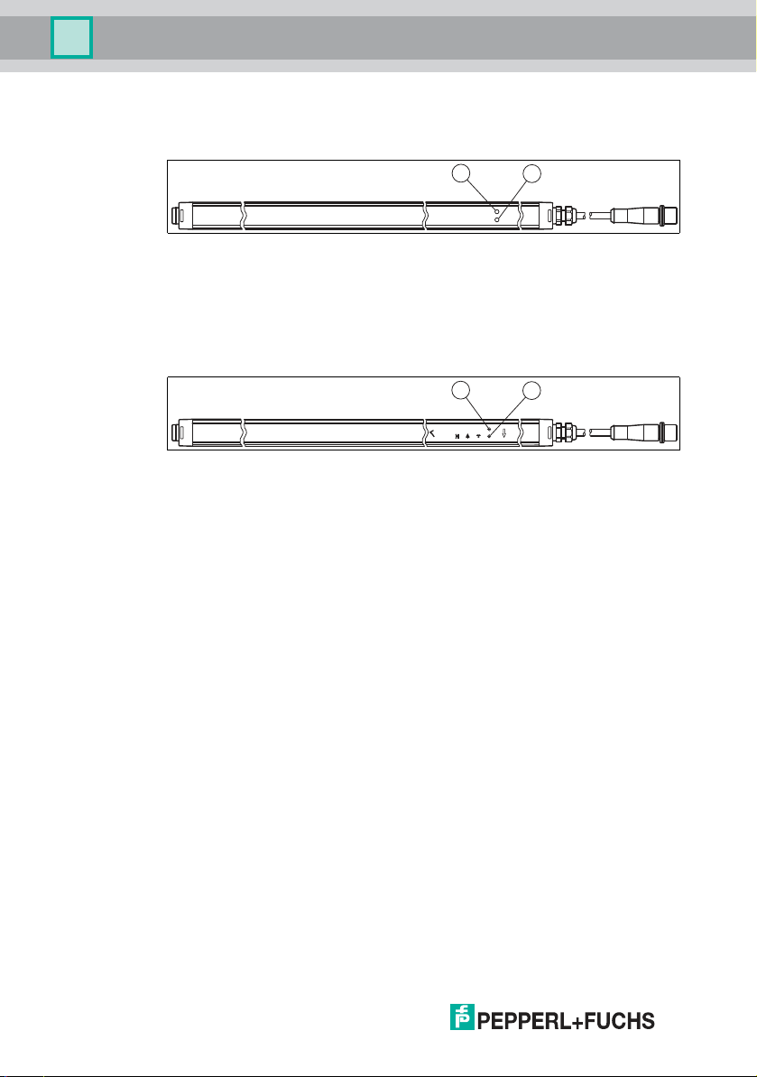
Product De scription
Figure 4.3 Touch field: Functi on indicators on the receiver strip
Touch buttons
1 Menu button Function selecti on
12 OK butto n Function confirmation
Function status ind icators, level 1
4 Detection field status
and object teach-in
switching output
5 Height output 1 Teach in height 1 o r display taug ht-in hei ght 1
6 Height output 2 Teach in height 2 o r display taug ht-in hei ght 2
7 Height output 3 Teach in height 3 o r display taug ht-in hei ght 3
8 Object p ositio n Object detec tion for moving objec ts
9 Crossover Beam crossover active
10 Object to lerance Tolerance beam for obj ects active
239596 2019-09
11 F2 Activate s econd level
Function status ind icators, level 2
4 Q (F2) Beam suppre ssion (blank ing) for inter fering object s
5 H1 (F2) Inverse operation (gap detection)
6 H2 (F2) Light-on or d ark-o n switchi ng type
Teach in objec t or dis play object det ection
Object detec tion for static objects
Beam crossover deactivated
Tolerance for obj ects deactivated
11
Page 12
LGS Series
1
3
4
2
1
4
6
7
8
53
2
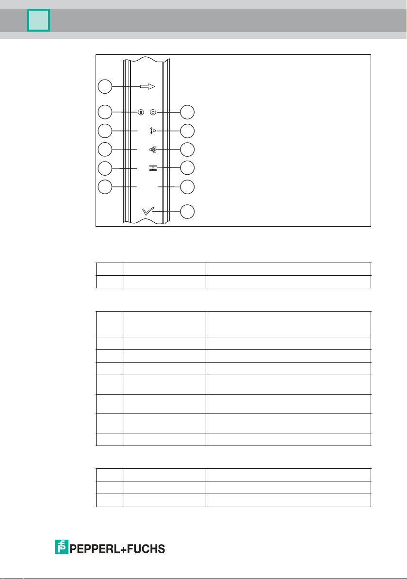
Product De scription
7 H3 (F2) Reset factor y setting
8 Object positi on (F2) Signal tracking acti ve
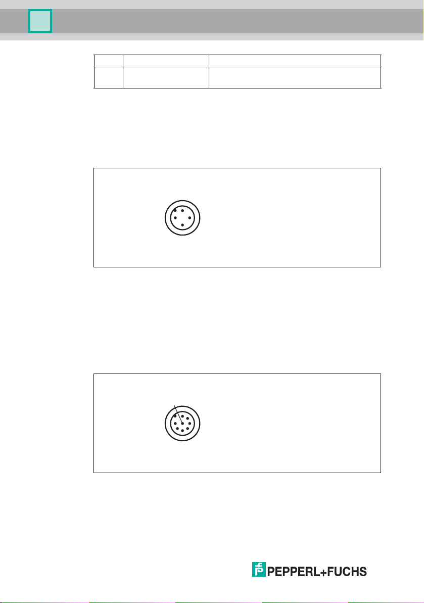
4.3 Interfaces and connections
The electrical connections are established usin g two M12 connectors. The
transmitter strip has a cable with a 4-pin conne ctor and the rec eiver strip a cable
with an 8-pin connector.
Transmitter s trip
Figure 4.4 Emitter unit connection layout
1 24 V DC
2 R ange (In)
3 0 V DC
4 T est (In)
Signal tracking inac tive
12
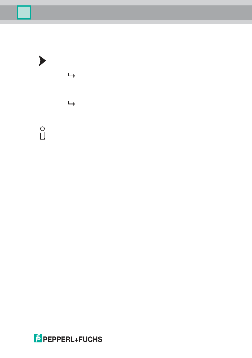
Receive r strip
Figure 4.5 Receiver strip connection layout
1 + UB
2 S C (Stability Contr ol, Out)
3 0 V DC
239596 2019-09
Page 13

LGS Series
Product De scription
4 C/Q (IO-Link / Out)
5 H1 (O ut)
6 H2 (O ut)
7 H3 (O ut)
8 Teach-in (In)
IO-Link communication is established via the C/Q connector (pin 4).
4.4 Accessories
An extensive range of accessories w ith detailed descriptions can be foun d in t he
appe ndix see chap ter 10.5 .
4.5 Scope of Delivery
The scop e of deliver y includes:
■
Emitter strip and receiver strip
■
Manual
■
Cable lug an d spare housing screw
Fixtures and cab les are not included in the scope of delive ry. S ee the appendix or
visit http://www.pepper l-fuchs.com for a selection of c ompatible mounting aids
and r ecommended cables.
239596 2019-09
13
Page 14
LGS Series
Installation
5 Installation
5.1 Preparation
Unpacking the Device
1. Check the p ackaging and con tents for d amage.
In the event of dam age, inform the shipping co mpany and notify the
supplier.
2. Check the p ackage contents against your order and the shipping do cuments
to ens ure that all items are presen t an d correct.
Should you have any q ues tions, direct them to Pepperl+Fuchs.
3. Retain the original pa ckaging in case the d evice is to b e stored o r shipped
again at a later date.
Note
Preven ting Extraneou s Light and Reflections
Situations in whic h the receiver is exposed to power ful extraneous light (e.g., from
flashing lamps or direct sunlight) must b e avoided. The influenc e of other optical
sens ors should also be prevent ed thro ugh s uitable positioning o r the use of
par titions. There must be n o reflective surfaces in the detection field, sinc e
reflections may prevent the detection of objects.
5.2 Mounting
Remember to kee p the detection field free of o bstac les wherever poss ible. The
first or last bea m in par ticular is used for visual synchron ization between the
emitter strip and the rece iver strip. If both synchronous beams are interrupted, the
detection field is no longer measured.
239596 2019-09
13
Page 15
Q
H1
Fix
H2
H3 Fn
Transmitter
Detection field + 159
n Beam
1. Beam
Receiver
Detection field
5
21.2 137.8
20
30.5
LGS Series
Installation
Figure 5.1 Light Grid Dimensio n Drawing
To mount the slim panels, use customized bore holes (d = 4.5 mm for M4 screws)
or a rear, continuous groove (for flat M6 nuts in accordance with ISO 4035).
Various fixtures are available for mounting the light grid see chapter 10.5.1.
Mounting Using the Rear Groove
There is a continuous g roove located on the r ear of the strip on the ligh t grid.
Standard flat M6 nuts in accordan ce with DIN 4 035 fit into this gro ove. Once these
nuts have been inse rted , they can b e use d to mou nt the light grid.
Mounting Using Holes D rilled by the Customer
The light grids can be mounted using user-defined holes. The ma ximu m screw
size is M4. Make sure you follow the instru ctions whe n po sitioning the hole.
Improper handling can damage the interna l electronics.
Drilling Holes
1. Mark the pos ition of the holes. Focus on the continuous line on the side of the
light grid .
2. Mark the p osition of the holes.
3. Using a 4.5 mm diam eter drill, drill all the way through the hous ing.
4. Deburr the hole.
5. Repeat the first steps until all ho les have been drilled.
6. Make sure that the aluminum chips do not scratch the optical surface.
14
239596 2019-09
Page 16
LGS Series
9
Installation
Secure the light grid in its final position using the drilled holes.
Figure 5.2 Position of the central point for the mounting holes
Figure 5.3 Mounti ng ho les
Mounting
1. Align the em itter strip and rece iver s trip so the y are parallel with one another
and at the same height.
2. The strips must be aligned with one another with an accuracy of
approximately ± 5°.
3. During mounting , ensure that the two strips have the same orientation. (Cable
outlet facing eith er upward or downward on both strips.)
4. The maximum d etection range must not be exceeded.
239596 2019-09
15
Page 17

LGS Series
Offset Y [mm]
Distance X [m]
Characteristic response curve
800
700
600
500
400
300
200
100
0
0 1 2 3 4 5 6 7 8
x
y
E1 S1 S2 E2
Installation
Figure 5.4 Maximum offset between emitter and receiver
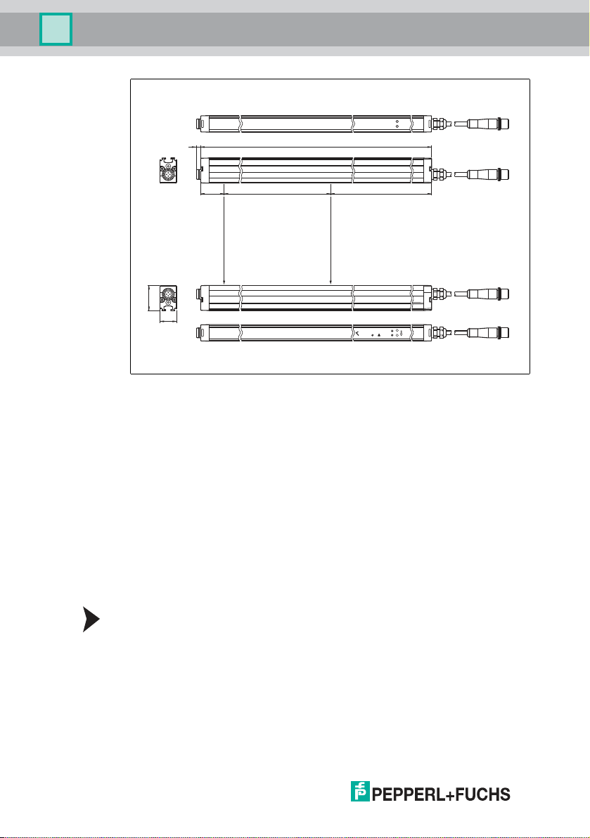
5.3 Multiple Positions
Note
If several light grids are operating close to each other, care must be taken to
prevent cross-talk. This can be achieved by swapping the emitter an d receiver, or
by ensuring a sufficient distance between the two light grids.
The illustration below indicates how to m ount two light grids with a swapped
emitter and receiver.
16
Figure 5.5 Multiple assi gnment of two pair s of lig ht grid s
239596 2019-09
Page 18

LGS Series
1
3
4
2
Installation
5.4 Connecting the Sensor Rails
Caution!
Elec trical connection
Wiring work tha t requires the op ening an d closing o f elec trical connections m ust
always be per formed with the power disconnected.
Use a Class 2 power supply to s upp ly the power (certified according to UL 1310).
Connecting the Emitter Strip
Figure 5.6 Emitter unit connection layout
1 24 V DC
2 Range (In)
3 0 V DC
4 Test (In)
Connect the emitter strip after the top pinout. Insulate the unused wires. See the
switching example sho wn on the following pag e see Figure 5. 8 on page 19.
Range input
The transmitter strip has a range input (pin 2) that adapts the transmitting power to
the relevant sensing range in the application. The trans mitte r attains a maximum
sens ing range of 1.6 m (or 2 m with option /35) if the input is open. If the
app lication requ ires a longer sensing range (6 m or 8 m with /35), the input
mu st be connect ed either to + UB or 0 V. The reduction in the tran smitting
power also preven ts extrane ous light from interfering with other sensors located in
the direct vicinity.
Test input
The transmitter strip has a test input (pin 4) tha t can be used to test th e function of
all switching outputs on the system by activating the test input or operate the
system in energy-saving mode. The inp ut can be connected either to + UB or 0 V.
239596 2019-09
17
Page 19

LGS Series
1
4
6
7
8
53
2
Installation
Conne cting the Receiver Strip
Figure 5.7 Receiver strip connection layout
1 + UB
2 S C (Stability Contr ol, Out)
3 0 V DC
4 C /Q (IO-Link / Out)
5 H 1 (Out)
6 H 2 (Out)
7 H 3 (Out)
8 T eac h-in (In)
■
Function tes t: When the strip is activated for le ss than 1.2 s, the
transmitter beams switch off and the outputs on the receiver strip switch on
in the same way as when a beam is interrup ted. The outputs for the height
control can also b e tested in this way, if the relevant h eight control
parameters are available.
■
Energy-saving mode: If the test input is activated for longer tha n 1.2 s, the
system switches to ener gy-saving mode with minimal energy c onsumption
and no func tions. The light grid reverts back to normal mode immediately
when the test input is dea ctivated .
18
Conne ct the receiver strip after the top pinout. All ou tputs are s hort-circuit pro of.
Insulate the u nused wires. See the switch ing example shown on the followin g
page see Figur e 5.8 on page 19.
Stability C ontrol Output (SC)
The SC switching output indicates an insufficient functional reserve and makes
status indicator 3 flash at 4 Hz with a delay of 5 seconds. T he SC switching output
only switches off o nce there is sufficient functiona l reserve again, for example, if
the front lenses are cleaned or the strips are read juste d.
Switching Output (C /Q)
This signal output is active (switch ed o n for da rk on, opp osit e for light on) if an
object is within the detection ran ge, or if a t aught-in object is detected . This is
shown by status indicator 3 and 4 respectively.
239596 2019-09
Page 20

LGS Series
24 V
0 V
Test
Transmitter strip Receiver
strip
24 V DC
Stability Control
0 V
C/Q
HQ1
HQ2
HQ3
Teach-In
24 V
Range
0 V
Test
Test
RangeRange
Menu buttonOK button
1
2
3
4
5
6
7
8
1
2
3
4
Installation
Height Control Outputs (H1 , H2, H3)
These three indepen den t signal outputs are active if objects in the detection field
match the position of the taug ht-in heigh t controls see c hapter 7.1.2. The outputs
then report the same statuses as the function status indic ators 5 (H1), 6 (H2), and
7 (H3 ). If no height controls are parameterized, the sign al outputs are always
inactive.
Connecting External Operating Buttons (Teach-In Input)
The receiver strip is equipped with a teach-in input. This input can be us ed to
route out the two operating buttons and to connect them externally. The function
of the me nu bu tton is connected via an external normally-op en contact to + UB.
The OK b utton is connected via an external no rmally-op en contac t to 0 V. To
prevent a short circuit when both normally-open con tacts are actuated
simultaneously, a 1 k /2 W resistor must be installed b etween the NO con tact
and 0 V.
Parameterization can be locked to prevent the menu button being pressed
unintentionally (keybo ard lock). To do this, set the external teac h-in input
permanently to + UB.
Switching Example
The LEDs on the o utputs are o ptional.
Figure 5.8 Connection example LGS
239596 2019-09
Grou nding/Shielding
The system does not require grounding in stand ard cases. If EMC faults occur,
use a grounding cable with the cable lug supplied in the scope of delivery. The
groun ding/shielding must always be moun ted on the receiver str ip. This is purely
functional grou nding rather than pro tective grou nding. It acts solely as a down
conductor for cab le-related faults and is not subject to any safety guidelines (e.g.,
personnel protection ).
Ground/s hield the d evice as follows:
19
Page 21

LGS Series
Installation
1. Make up a groundin g cable (max. 1 mm2) using the s upp lied cable lug.
2. Remove one housing sc rew from the cover at the cab le end, us ing a Torx T8
screwd river.
3. Place the cable lug with the prepare d cable und er the cove r and tighten the
housing screw again.
4. Connect the other e nd of the g roun d cable to adjacent metal compone nts
(e.g., mount ing b ase, frame, etc.).
The sens or is now grounded.
5.5 Storage and Transportation
Keep the original packaging. Always store and transp ort the device in the original
packaging.
Store the device in a clean an d dry environment. The pe rmitted ambient
conditions m ust be co nsidered, see da tasheet.
20
239596 2019-09
Page 22

LGS Series
Commissioning
6 Commissioning
6.1 Final Assem bly
Checkin g the Mou nting an d Settings
1. Check the position of th e ligh t strips in relation to o ne anot her. The emitter
strip an d receive r strip must be a ligne d with one another with an accuracy
of approximately ± 5°.
2. The light strips ca n be opera ted briefly to che ck that the final asse mbly has
been performed correctly. The light strips are a ligne d perfectly with each
other when the yellow status LED on the receiver strip does not light up continuously or flash.
3. Now secure the light strips. Check all screw connections and tighten as necessary.
4. Check the cabling, referring to the wiring diagrams.
Remember to kee p the detection field free of o bstac les wherever poss ible. The
first or last bea m in par ticular is used for visual synchron ization between the
emitter strip and the rece iver strip. If both synchronous beams are interrupted, the
detection field is no longer measured.
The sign al needs t o be calibrat ed to ac hieve the bes t possible resolution for the
relevant application. Therefore, after a ny m odifications to the ap plication
(installation situation), s tart the system to recalibrate the signal and maintain the
sam e level of availability.
The sign al output respond s to detected objects, h eavy s oiling on t he lenses, or
misaligned profiles. The electronics compe nsate for s ignal changes caused by
grad ual soiling or temperature changes. If a minimum o f one light bea m is
inter rupted, the output rem ains active until the light bea m is interrupted (with dark
on) or soiling is detected.
6.2 Commissioning the Light Grid
Commissionin g
1. Check that the light grid is in the co rrect position.
2. Switch on the supply voltage. The operating status indicators on the emitter
strip a nd receiver strip light up green.
3. If the status LED is n ot lit, the light grid is aligned. The status L ED lights up
when the device is misaligned or an object is detected.
The two s trips are per fectly aligned with one another and can now b e
configured see chapter 7.1.
To commiss ion and operate the light grid via th e IO- Link inter face, please refer to
the following sec tion see chapter 7.2.
239596 2019-09
21
Page 23

LGS Series
Operation
7 Operation
7.1 Operating the Light Grid
No objects o r he ight controls are p arameter ized on delivery.
The grid is o perated using the to uch field o n the front of the receiver strip. The
system can be parameterized as required using the two operating elemen ts and
the icons on the receiver strip. Parameterize the light grid by pres sing the menu
button. The "Q" ico n flashes in parame teriza tion mode.
■
Rapid flashing means: The function is not yet activated /taugh t in (the LED
turns on briefly a nd then turns o ff for a long period)
■
Slow flashing means: The function is activated/taught in (the LED tur ns on
for a long per iod and then turns o ff br iefly)
Pressing the menu button again activates a ll parameterizable func tion s in
succes sion, and each relevant icon flash es b rightly.
To teach in or activate the current pa rameter, press the OK button .
For information on o pera ting v ia an externa l connection, see chapter 5.4.
If no operating buttons are presse d within a timeout p eriod of 30 s econds,
parame terization a utomatica lly e nds. Any previously mo dified parameters are
retained.
Factory Settings
To restore the factory settings, proceed as follows:
22
1. Press the M enu button to enter parameterization mod e.
2. Press the Menu button repeat edly until the "F2" icon st arts flashing.
3. Press the Menu button . This will take you to the 2nd parameterization
level.
4. Press the Menu bu tton repeat edly until the "H3 " icon starts flashing .
If you now press the OK button , the light grid will be restored to its
factor y settings.
239596 2019-09
Page 24

LGS Series
Operation
Factory Se tting
Parameter Status
Heig ht control 1 – 3 Inactive
Beam cross over (3-way) Active
Objec t positio n Floating
Objec t tolerance Active
Light-on/dark-on switching Dark on
Beam supp ression (blanking) Inactive
Inverse oper ation (gap d etectio n) Inactive (solid objects )
Signal track ing Inactive
Table 7.1 Factory settings of the light grid
Parameterization Status Indicator
To display the cur rent statuses parameterized on the 1s t level, briefly pre ss the
OK button outside of the para meterization me nu.
This disp lays all the active functions for five seconds.
■
Icon dimly lit: Function has not been parameterized or is disabled
■
Icon b right and constantly lit: Function has been parameterized or is
activate d
The status of functions on the 2nd level can only be read wh ile the relevan t
function is being parameterized:
LED flash ing quickly = function disa bled
LED flash ing slowly = fun ction ena bled
239596 2019-09
23
Page 25

LGS Series
Operation
Touch Field Overview
24
Figure 7.1 Touch field on the sensor for parameter izatio n
239596 2019-09
Page 26

LGS Series
Operation
Touch Field: Configurable Parame ters, 1st Leve l
Param eter
Q ob ject Q Explanation of fun ction: Teach in objec t. The
Heig ht
control 1
Heig ht
control 2
Heig ht
control 3
Objec t
positi on
Beam
crossover
Objec t
tolerance
Touch field
icon Description
object c urrentl y located in the detection field is
taught i n. Output Q is ac tivated when the object is
detected dur ing operation. The "Q" icon lights up
brightly to indi cate this status.
Detection fie ld vacant: If the detection field is
vacant when the OK butto n is pressed, any ob ject
previously taught in will be deleted and the
Q switching outp ut will respond to any interruption in
the beam.
Display function: The "Q" icon sig nals each
interruption in the detection field in parallel to status
indicator 3.
H1 Explanation of fun ction: Teach in objec t height.
H2 Function as des cribed for height control 1.
H3 Function as des cribed for height control 1.
The upp ermost beam interrupted by the object
currently located in the detection field is taught in as
the height control. The H1 output switches on
whenever this b eam i s interrupted duri ng operation.
The "H1" ico n lights up b rightly to indicate this
status.
Synchronizatio n interrupted: Th e H1 output
switches on if synchroni zation is lost, even if there is
no correspondi ng object loc ated in the detectio n
field.
Detection fie ld vacant: If the detectio n field is
vacant when the OK butto n is pressed, any height
control previously taught in wi ll be d eleted and the
H1 switching output will no longer resp ond.
The H2 switching output is activated .
The H3 switching output is activated .
Explanation of fun ction: Type of objec t position.
The ob ject position is "floating " in the factory setti ng.
Change function: Pressi ng the OK button changes
the object pos ition of a taught-in object from
"floatin g" to "fixed."
Reset function: Pressing the OK bu tton again sets
the object pos ition to "floating" again.
Beam crossover is ac tive in the factory setting.
Change function: Pressing the O K button dis ables
beam crossover.
Reset function: Pressing the OK bu tton again
enables beam c rossover again.
Explanation of fun ction: When object toleranc e is
activated , this permi ts a devi ation in the relevant
object s izes of a resolution unit and improves ob ject
detection when beams are interrupted due to
vibrations. The tolerance app lies to both beam
suppress ion (blanking ) areas.
Object tolera nce is active in the fac tory setting .
Change function: Pressing the O K button dis ables
active tolerance of a resolution unit for object
detection.
Reset function: Pressing the OK bu tton again
enables object tolerance again.
239596 2019-09
25
Page 27

LGS Series
F
2
F
2
F
2
F
2
F
2
Operation
Paramete r
2nd parameter
ization level
Table 7.2 Touch field: configurable param eters, 1st level
Touch field
icon Description
Enable fun ction : Pressing the OK button enables
the 2nd parameterization level.
Disable function : Pressing the OK button again
quits the par ameterization proces s.
Touch Field: Config urable Parameters, 2nd Leve l
Paramete r
Beam
suppress ion
(blanking )
Inverse
operation (gap
detection)
Light-on/darkon switc hing
Reset factory
setting
Touch field
icon Description
Explanation of fun ction: Any beams detec ted
within t he taught-in object area during operation do
Q
H1
H2
H3
not trigger a switching element function.
Teach in obje ct: Press the OK button: The object
currently locate d in the detecti on field is taught in as
beam supp ression.
Two different areas can be taught in simu ltaneo usly.
However, at least one of the two outer synchronous
beams must remain free.
If the detection field is vacant when the OK button is
pressed , any previously taught in beam suppr ession
area is deleted again.
The p arameter can be modified before or after
teachi ng in an objec t.
Object type detection is set to "solid " in the factory
settin g.
Modify: Pressing the OK but ton mod ifies the objec t
type of a taught-in ob ject fro m "solid" to "inverse" for
gap detection.
Reset: Pressing the OK button again sets obj ect
type detection to "solid" again.
Explanation of fun ction: Dark on: The switching
output is activated when beam s in the detection field
are interrupted (or the re is no synchronizatio n with
the emitter).
Light on: The switching output is acti vated when the
detection field is vacant.
The switching type is set to "da rk on" in the factory
settin g.
Enable fun ction : Pressing the OK button changes
the switc hing type of all Q, H1, H2, H3 switc hing
outputs from "dark on" to "l ight on."
Disable function : Pressing the OK button again
sets the switching type to "dark on" again.
Pressing the OK bu tton resets all parameters to the
factory setting.
Pressing the menu button again instea d qui ts the
parameterization pr ocess.
239596 2019-09
26
Page 28

LGS Series
F
2
Operation
Param eter
Signal track ing
Table 7.3 Touch field: co nfigurable parame ters, 2nd level
Touch field
icon Description
Explanation of fun ction: In non-stable ambient
conditions, e.g., soili ng and temperature changes,
Object
position
signal tracking ensures that the response threshold
remains constant. Reflective obje cts that are
occasionally present along the detection fiel d can
distor t signal tracking and caus e switchi ng faults. In
the wor st-case scenario, permanent detec tion is
signaled even though there is no object in the
monitoring fiel d. In this case, the function must be
disabled.
Signal tracking is inactive in the factory setti ng.
Enable func tion: Pressing the OK button enables
signal tracking.
When signal tracking is enabled, the specifi ed
resolution is r eached. The value of the switchi ng
threshold is set to 60 %.
Paramete rization via IO-Link
Parameterization via IO-Link allows the resp onse
threshold and signal track ing to be defi ned
independently of each other.
=> Without tracking: The response threshol d can
be selec ted in 10 % increments between
0 = m inimum thres hold, 1 = 10 %, and 9 = 90 %.
■
0 = minimum threshold, no tracking, maximum
gain, default value
■
1 = 10 % of value of response thres hold, no
track ing
■
2 = 20 % of value of response thres hold, no
track ing
■
...
■
9 = 90 % of value of response thres hold, no
track ing
=> With tracking: The re spons e threshold ca n be
freely selected between 10 % ... 90 %. This allows
customized configu ration between fine resolution
(high threshold) and high immu nity to reflective
objects (low threshold).
■
10 % … 90 % = value for response threshol d that
can be freely sel ected, with tracking
Disable function : Pressing the OK button again
disables signal tracking.
When signal tracking is di sabled, the lowes t
switching threshold is configured. The optical
resolution is increas ed by 4 m m.
7.1.1 Object detection (overha ng control)
The LGS switching light grid uses th e factory settings a nd does not require any
further parameterization. Switchin g output Q reacts to every single object in the
detection field.
Possible application-spe cific settings:
■
Deactivate beam crossover
■
Beam suppr ession (blanking) of permanen t installations in the detection
field
■
239596 2019-09
Set switching mod e of outputs to light on
27
Page 29

LGS Series
Operation
7.1.2 Monitoring the object height with height controls
The LGS switching light grid has been designe d e.g. to monitor the load heights of
pallets. An H switching outp ut is t herefore allocated for every load height. For
example, the up per edge of the sm alles t object is taugh t in as height control 1
(H1), the upp er edge of the middle object as height control 2 (H2) and the up per
edge of the largest object as h eight control 3 (H3). No height output will switch on
for any ob ject smaller than height control 1. Only output H1 will switch on for
objects larger than or equal to height control 1 b ut smaller than heigh t control 2.
Larger o bjects will trigger outputs H2 and H3 as well. The assignm ent of more
than one beam to a height control is only possible via IO-Link. Switching output Q
is activated every time an object is detected.
Possible app lication-specific setting s:
■
Deactivate be am crossover
■
Beam supp ression (blanking) of permane nt ins tallations in the detection
field
■
Set switching mod e of outp uts to light on
28
239596 2019-09
Page 30

LGS Series
Operation
7.1.3 Object identifi cation
The switching light grid ca n identify solid or pe rforated objects in the de tection
field from the interrupted light beams. Output Q is switched f or the entire t ime that
the objec t is in the d etection field.
The object ca n also be set to a floating or fixed location in the detection field. If a
fixed p osition is conf igured , output Q will only switch o n if the identified o bjec t is
exactly at this taught location. The invers e ob ject identification operating mo de is
intended to detect ho les, e. g., in plates. Either individual holes or contiguous hole
patterns can be detected. The position of the outer edg e of the plate in the
detection field is irrelevant.
Possible application-spe cific settings:
■
Deactivate beam crossover
■
Beam suppr ession (blanking) of permanen t installations in the detection
field
■
Set switching mod e of outputs to light on
239596 2019-09
29
Page 31

LGS Series
Operation
7.2 Commissioning and Operating the Light Grid with IO-Link
Commissioning with IO-Link
To activate the sensor via the IO-Link, p roceed with the following steps:
1. Set the corresponding port on the IO-Link master to which the sensor is connected to IO-Link status.
2. When commun ication is succe ssfully established, the green operating
indicator flashes with short interrup tion s every second.
The sens or now transmits process d ata and can be parametrized or
diagnosis can be run.
Use preset p arameters to c onfigure, par ameterize, and d iagnose the se nsors. To
parame terize the sensors with an engineer ing to ol, u se the device description
(IODD), which can be load ed into all system environments with IO-Link support.
To operate the sens or in an FDT enviro nment, you can also use a DTM.
30
239596 2019-09
Page 32

LGS Series
Operation
See the d evice description and software, e.g., the IODD, DTM, and the FDT
mas ter ap plication within the p roduct at www.pe pperl-fuchs.com/io-link.
239596 2019-09
31
Page 33

LGS Series
Maintenance and Repair
8 Maintenance and Repair
8.1 Maintenance
To get the best possible performance out of your device, clean the optical unit on
the device when necessary and always keep it clean.
When c leaning the optical unit yo u sho uld note the following :
■
Do not touch the optical unit w ith your fingers.
■
Do not imm erse the d evice in water. Do not spray th e device with water or
other liquids.
■
Do not use a scouring agent to clea n the surface of the d evice.
■
Use a cotton or paper cloth moistene d with water or isopropyl alcohol. The
cloth must not be soaked!
■
Remove any residual alco hol using a cotton or paper cloth moistened w ith
distilled water. The cloth m ust not be soa ked!
■
Wipe the device s urfaces d ry using a lint-free cloth.
8.2 Repair
The device must not be repaired, changed, or manipu lated. In case of failure,
always replace the device with an original device.
Note
If it appe ars that safe operation of th e sens or system is no long er possible, it must
be taken out of ope ration and secured against inad vertent use.
32
Always send both parts o f the d evice (transmitter and receiver strip) to
Pepperl+Fuchs together for repa ir.
239596 2019-09
Page 34

LGS Series
Troubleshoot ing
9 Troubleshooting
9.1 Troubleshooting
Before requesting field service, check that th e following actions have been
taken:
■
The plant h as been tested according t o the following check lists.
■
Telephone assistance obtained from the Service Cen ter to isolate the
problem .
Interference
■
The sensor must be firmly m ounted. It m ust not vibrate.
■
The sensor must not be installed behind a cover.
■
The sensor should be installed so it is protected from rain.
Eliminating Interference
Sour ce of fault Cause Action
Emit ter:
Status ind icator flashes
quickly at 8 Hz
Receiver:
Operating indi cator (green)
flashes in pulses at 0.8 Hz
Receiver:
Operating indi cator (green)
flashes at 4 Hz
Receiver:
Status ind icator flashes at
4 Hz
Receiver:
Status ind icator flashes
quickly at 8 Hz
Receiver: Switching
output with detection signal
although there is no object
in the detec tion field
Non-specific flashi ng of the
indic ators on the light grid
Fault state 1. Check the operating
Low voltage Check the o perating
Short circuit at the outp uts Check the wiring a t the
Insuffic ient functi onal
reserve
Fault state during signal
meas urement
Reflective objec ts parallel
to the detect ion field
voltage.
2. Switch the voltage off
and on again.
voltage.
outputs.
Clean the fro nt pane ls;
adjust the em itter and
receiver.
1. Check the op eratin g
voltage.
2. Switch the voltage off
and on again.
Deactivate signal tracking
(2nd level, object pos ition).
Switch the voltage off and
on again.
■
If none of the sug gestions above c orrec ts th e problem, please co ntact the
Service Center.
Load factory setting
Factor y Setting s
To restore the factory s ettings, p roceed as follows:
1. Press the Menu button to enter para meterization m ode.
239596 2019-09
33
Page 35

LGS Series
Troubleshoot ing
2. Press the Menu button repeat edly until the "F2" icon st arts flashing.
3. Press the Menu button . This will take you to the 2nd parameterization
level.
4. Press the Menu bu tton repeat edly until the "H3 " icon starts flashing .
factor y settings.
If you now press the OK button , the light grid will be restored to its
34
239596 2019-09
Page 36

LGS Series
Appendix
10 Appendix
10.1 Technische Daten
General specifications
Effective detec tion
range
Threshold detecti on
range
Light sour ce IRED
Light type modulated in frared light , 8 50 nm
Fiel d height See chap ter 10.3
Beam cross over Factory set ting: three beam crossing, deactivateable
Beam blank ing adjustab le max. 2 fixed sup pressib le beam areas (blanking)
Beam spac ing LGS8 = 8,33 mm; LGS17 = 16,67 mm; LGS25 = 25 mm;
Number of beams See chap ter 10.3
Operating mode Emitte r: Emitter power adjustable in tw o ranges
Optic al reso lution withou t beam crossover: see beam spac ing
Angl e of divergence 10 °
Ambi ent light limit > 50000 Lu x (if external light source is outs ide the opening
Standard : 0.3 ... 6 m
Option /35: 0.5 ... 8 m
LGS100: When beam crossover i s activated, the detection
range starts at 0.6 m
Standard : 7.5 m
Option /35: 10 m
LGS50 = 50 mm; LGS100 = 100 m m
with beam crossover: 4 / 8,5 / 12,5 / 25 / 50 mm .
Only between 25 % ... 75 % of range
angle)
Functional safety related parameters
LGS8 LGS17 LGS25 LGS 50 LGS100
MTTF
d
Miss ion Time (TM) 20 a 20 a 20 a 20 a 20 a
Diagnostic
Coverag e (DC)
21 a 25 a 34 a 56 a 7 8 a
60 % 60 % 60 % 60 % 6 0 %
Indicators/op erating means
Operation indica tor Power on: LED green, staticall y lit , Und ervoltage indicator :
Function indicator Emitter: Yellow LE D, illuminates at high emitting power, off a t
Control elements Receiver: 2 touch buttons for programming
239596 2019-09
Green LED, pulsing (ap prox. 0.8 H z) , short-c ircuit : LED
green flas hing (approx. 4 Hz )
low emittin g power
Receiver: Yellow L ED: illuminates when an object is detected
flashes when falling short of the stabi lity control (4 H z)
Error message: Yellow L ED flas hes (8 Hz) in emitter and
receiver
35
Page 37

LGS Series
Appendix
Electrical specifications
Interface
Input
Output
Operating voltage 18 ... 30 V DC
Ripple 10 %
No-loa d supply cu rrent Emitter : 50 m A
Interface type IO-Link
Protoco l IO-Link V1.0
Mode COM 2 (38.4 kBaud)
Test input Emi tter sw itch-off with +UB or 0 V at pin 4 (em itter)
Function input Range input activation from 1.6 m (or 2 m in case of option
Pre-fault indicati on
output
Switching type Factory setting: dark ON , Switc hable to light ON mode
Signal output Switch output (detecti on field C/Q) 1 push-pul l (4 in 1) output,
Switching threshold Factory setting: The signal tra cking for the thresho ld value is
Switching voltage max. 30 V DC
Switching current max. 100 mA
Voltage drop 2 V DC
Switching frequency max. 118 Hz, see datas heet
Response time Se e chapter 10.3
Timer function Off-del ay programmable from 0 ... 1.25 s in 5 ms steps
Receiver: 150 mA (without outputs)
/35) with +UB or 0 V on pin 2 (emitter)
Teach-In input for programming on pin 8 (receiver)
Stability Contro l (SC) 1 PNP, short-c ircuit protected , reverse
polarity protected on pin 2 ( receiver )
short-c ircuit protected , reverse polarity prote cted on pin 4
(receiver ),
Height monitoring (H1, H 2. H 3) 3 push-pull (4 in 1) outputs ,
short-c ircuit proof, reverse polarity protected on p in 5, pin 6,
pin 7 (receiver)
deactivated, increasi ng the opti cal resolution by a max imum
of 4 mm; switch able to active signal tracki ng
(adjustm ent via IO-Link only)
36
Compliance with standards and directives
Directive conformity
EMC Directive
2004/108/EC
EN 60947-5-2:2007
239596 2019-09
Page 38

LGS Series
Appendix
Standard conformit y
Product standard EN 609 47-5-2:2007
IEC 60947-5-2:2007
Approvals and c ertificates
Protection class III ( IEC 61140 )
UL approval cU Lus L isted
CC C appr oval CCC approval / marking not req uired for products rated 36 V
Ambient con ditions
Ambi ent temperature Stand ard : -10 ... 60 °C (14 ... 140 °F )
Storage temperature -30 ... 70 °C (-22 ... 158 °F)
Option /146: -30 ... 60 ° C (-22 ... 140 °F)
Mechani cal speci fications
Housi ng length L See chapter 10.4
Protection degree IP67
Connection Emitte r: 200 mm connecti ng cable with 4-pin, M12x1
Material
Housi ng extrud ed aluminum secti on , Silver ano dized
Optic al face Plastic pane , Polycarbonate
Mass See chapter 10.4
connector
Receiver: 200 mm connecting cable with 8-pi n, M12 x 1
connector Ca ble cross sec tion min. 0.25 mm2
Max. cable length 30 m
10.2 Type Code
Automation ligh t grids from the LGS series are designated using a code as
follows:
LGSx x-yyyy-IO/Options
Here, xxx indicates the resolution, y yyy indicates the height of the detection field,
IO indicates the integrated IO interface, and Op tions indicates a dditional op tions.
Resolution [mm]
xxx yyyy IO /35/110/115b/146
8 100, 300, … 2100 IO /35/110/115b/146
17 100, 300, … 3200 IO /35/110/115b /146
25 100, 300, … 3200 IO /35/110/115b /146
239596 2019-09
Detection field
[mm] IO-Link interface Options
37
Page 39

LGS Series
Appendix
Resolu tion [mm]
50 300, 600, … 3000 IO /35/110/115b/146
100 300 , 600, … 3000 IO /35/110/115b/146
Detection field
[mm ] IO-Link interface Options
Clarification of Options
/35 Increased detection rang e: 8 m instead of 6 m
/110 Push-pull 0.1 A switching output, short-circuit proof, protected against
/115b M12 plug with 200 mm co nnectio n cable (series)
/146 Extended temperature range: -30 °C instea d of -10 °C
reverse polarity (series )
10.3 Response Times and N umber of Beams
The mechanical beam spacing determine s the minimum detectable object size
(signal tracking active). By crossing the light beams, the reso lution of the light grid
increases by a max imum of 100 %. The inc reased resolution is available in the
area between 25 % ... 75 % of the detection range between the e mitter strip and
the receiver s trip. Make su re that all ob jects pass the e mitter strip or receiver strip
at this d ista nce. The crossover function is activated by default. Deactivating the
crossover func tion d oes not alter the response time.
Response time [ms]
Variants
LGS8100
LGS8300
LGS8600
LGS8900
LGS81200
LGS81500
LGS81800
LGS82100
Detection
field [ mm]
100 13 3 4 5 7
300 37 3 6 7 10
600 73 5 8 9 15
900 109 6 11 11 19
1200 145 7 13 13 24
1500 181 8 15 16 28
1800 217 9 17 18 33
2100 253 10 20 20 37
Number
of beams
C/Q output witho ut
object
parameterization
Typical Maximum Typi cal Maximum
C/Q o utput with
object
parameterization
Height control
outputs H1, H2, H3
38
239596 2019-09
Page 40

LGS Series
Appendix
Variants
LGS17100
LGS17300
LGS17600
LGS17900
LGS171200
LGS171500
LGS171800
LGS172100
LGS172400
LGS172700
LGS173000
LGS173100
LGS173200
Response time [ms]
C/Q outp ut with
Detection
field [mm ]
100 7 2 4 5 7
300 19 3 5 6 8
600 37 3 6 7 10
900 55 4 7 8 13
1200 73 5 8 9 15
1500 91 5 10 10 17
1800 109 6 11 11 19
2100 127 6 12 12 22
2400 145 7 13 13 24
2700 163 7 14 15 26
3000 181 8 15 16 28
3100 187 8 16 16 29
3200 193 8 16 16 30
Number
of beams
C/Q o utput without
object
parameterization
Typical Maximum Typi cal Maximum
object
parameterization
Height control
outputs H1, H2, H3
LGS25100
LGS25300
LGS25600
LGS25900
LGS251200
LGS251500
LGS25-
239596 2019-09
1800
100 5 2 4 5 6
300 13 3 5 5 7
600 25 3 5 6 9
900 37 3 6 7 10
1200 49 4 7 7 12
1500 61 4 8 8 13
1800 73 5 8 9 15
39
Page 41

LGS Series
Appendix
Variants
LGS252100
LGS252400
LGS252700
LGS253000
LGS253100
LGS253200
Response time [ms]
C/Q o utput with
Detection
field [ mm]
2100 85 5 9 10 16
2400 97 5 10 10 18
2700 109 6 11 11 19
3000 121 6 11 12 21
3100 125 6 12 12 21
3200 129 6 12 12 22
Number
of beams
C/Q output witho ut
object
parameterization
Typical Maximum Typi cal Maximum
object
parameterization
Height control
outputs H1, H2, H3
40
LGS50300
LGS50600
LGS50900
LGS501200
LGS501500
LGS501800
LGS502100
LGS502400
LGS502700
LGS503000
LGS100300
LGS100600
LGS100900
300 7 3 4 5 7
600 13 3 5 5 7
900 19 3 5 6 8
1200 25 3 5 6 9
1500 31 3 6 6 10
1800 37 3 6 7 10
2100 43 4 7 7 11
2400 49 4 7 7 12
2700 55 4 7 8 13
3000 61 4 8 8 13
300 4 2 4 5 6
600 7 2 4 5 7
900 10 3 5 5 7
239596 2019-09
Page 42

LGS Series
Appendix
Variants
LGS1001200
LGS1001500
LGS1001800
LGS1002100
LGS1002400
LGS1002700
LGS1003000
Table 10.1 Response times w ith and without objec t paramete rization
Detection
field [mm ]
1200 13 3 5 5 7
1500 16 3 5 5 8
1800 19 3 5 6 8
2100 22 3 5 6 9
2400 25 3 5 6 9
2700 28 3 6 6 9
3000 31 3 6 6 10
Number
of beams
10.4 Profile Length and Weight
Response time [ms]
C/Q outp ut with
C/Q o utput without
object
parameterization
Typical Maximum Typi cal Maximum
object
parameterization
Height control
outputs H1, H2, H3
Prof ile length and weight
Overall length of the
Detection field [mm]
100 260 200
200 360 250
300 460 300
400 560 350
500 660 400
600 760 450
700 860 500
800 960 550
900 1060 600
1000 1160 650
1100 1260 700
1200 1360 750
1300 1460 800
1400 1560 850
239596 2019-09
transmitter / receiver strip
[mm]
Weight of transmitter /
receiver strip [g]
41
Page 43

LGS Series
Appendix
Table 10.2 Profi le length and weight per strip
Overall leng th of the
Detection field [mm]
1500 16 60 900
1600 17 60 950
1700 18 60 1000
1800 19 60 1050
1900 20 60 1100
2000 21 60 1150
2100 22 60 1200
2200 23 60 1250
2300 24 60 1300
2400 25 60 1350
2500 26 50 1400
2600 27 60 1450
2700 28 60 1500
2800 29 60 1550
2900 30 60 1600
3000 31 60 1650
3100 32 60 1700
3200 33 60 1750
transmitter / receiver strip
[mm ]
Weight of transmitter /
receiver strip [g]
10.5 Accessories
10.5.1 Installation accesso ries
The following products are available as mo unting ac cessories:
42
239596 2019-09
Page 44

LGS Series
Appendix
Compatible mounting acce sso ries for the light grid
No. Des ignation Illustration Description
1 OMH-S LCT-01 Mounting bracket
2 OMH-LGS-01
3 OMH-S LCT-03 Mounting bracket
4 OMH-S LCT-04 Mounting bracket
5 OMH-S LCT-05 Mounting bracket
Only in
combination with
OMH-S LCT-01
Mounting bracket
239596 2019-09
43
Page 45

LGS Series
Appendix
Table 10.3 Accessories list
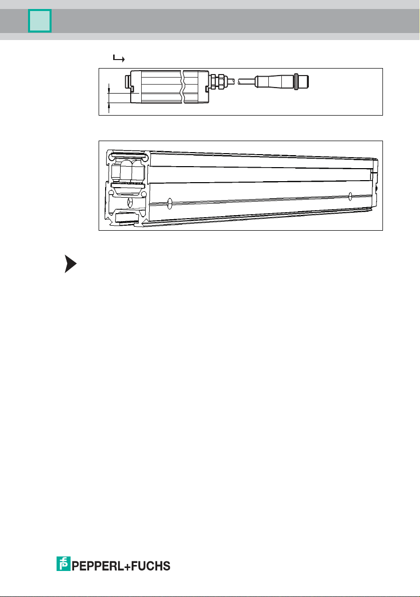
Mounting Aid OMH-SLCT -01
Model number: OMH-SLCT-01
The emitters/receivers can be secured using mou nting aids that grip the dove tail
guide. There are dovetail guides o n three sides of the profile. When mounting and
aligning the unit, avoid subjec ting the profile to mechanical tension.
A minim um of two mounting aids must be used to se cure the emitter or receiver. If
vibrations or shoc ks are expected, we recommend a ttach ing mounting aids at
intervals of 500 m m.
Mounting Aid OMH-LGS-01
Model number: OMH-LGS-0 1
The OMH-LGS-01 mounting aid acts a s a f ixed be aring and sec ures the position
of the light curtain in t he event of t hermal expansion , mechanical vibration, or
shock.
No. Designatio n Illustration Desc ription
6 AA SLCT-01 Profile alignment
tool
44
239596 2019-09
Page 46

LGS Series
ø 4.3
8.3
16
ø 4.3
7228
OMH-LGS-01
OMH-SLCT-01
38.6
45.4
42.8
53
OMH-LGS-01
OMH-SLCT-01
Appendix
Figure 10.1 Dimensional drawin g and fitting mounting accessory OMH-LGS-01
Figure 10.2 Alignment aid
Orde r code: AA-SLCT-01
The trans mitte r and receiver should always b e aligned at the same height in
parallel to one a nother. The AA-SLCT-01 alignm ent aid with bub ble level assists
the perpendicular alignment of the profile. The AA-SLCT-01 alignment aid is
simp ly clipped into the gr oove o n the side of the profile.
239596 2019-09
45
Page 47

LGS Series
ø 21
24.5
11.1
ø 5.5
20
139
14
23.4
21.5
PUSH
PUSH
Appendix
Figure 10.3 Dimensional drawing and assembly of the alignment A A-SLCT-01
10.5.2 Connecting Ca bles
Various 4-pin and 8-pin connec ting cables are available in different cab le lengths.
Conne cting cables for automa tion light grids
Use Model number
Length 2 m Length 5 m Length 10 m Length 15 m
4-pin cable
(transm itter
strip)
8-pin cable
(receiver strip)
V1-G-BK2MPUR-UL
V19-G -BK2MPUR-IEC
10.5.3 Accessories for IO-Link Operation
The following accessories are available for operat ing the receiver strip in IO-Link
mode.
Designation Descripti on
IO-Link-Master02-USB IO-Link master param eterization tool
46
V19-G-B K2M-PUR-UV1-G
Adapter cable for offli ne parameterization M12 x 1, 8-pin to
M12 x 1, 4-pin, length 2 m
V1-G-BK5MPUR-UL
V19-G -BK5M PUR-IEC
V1-G-BK10M PUR-UL
V19-GBK10M-PURIEC
V1-G-BK15M PUR-U L
239596 2019-09
Page 48

LGS Series
Appendix
Desi gnation Description
IO Device Description Device d escrip tion on how to operate and control automation
IO Device Description
Interpreter
light grids via an IO -Link master
(available as a download on the product page)
IO Device Description interpreter and device type manag er
for use via IO Device Description within an FDT environment
10.6 Parameterizing the light grid
Parameterizing the light grid using a flow chart.
239596 2019-09
47
Page 49

Press menu button
Q Object pictogram flashes fast
Press menu button
Place object
in beam path
Press OK Button
H1 pictogram flashes fast
Place object
in beam path
Press OK ButtonPress menu button
H2 pictogram flashes fast
Press menu button
Place object
in beam path
Press OK Button
H3 Pictogram flashes fast
Place object
in beam path
Press OK ButtonPress menu button
no settings
Teach an object
Object has been taught
Teaching height
of object
no settings
Height of object
has been taught
no settings
Teaching height
of object
Height of object
has been taught
Teaching height
of object
Height of object
has been taught
no settings
LGS Series
Appendix
Figure 10.4 Parameterizing the l ight grid using a fl ow chart, left page
48
239596 2019-09
Page 50

LGS Series
floating = LED long light duration / short break
fixed = LED short light duration / long break
active = LED long light duration / short break
disabled = LED short light duration / long break
active = LED long light duration / short break
disabled = LED short light duration / long break
no settings
no settings
no settings
Press menu button
2nd level
End of parameterization
2nd level pictogram flashes fast
Press menu button
Object tolerance pictogram
flashes fast
Press menu button
changed
change
changed
Press OK button
Object position pictogram
flashes fast
Press menu button
Selection
floating
or
fixed
change
changed
Press OK Button
Beam crossover pictogram
flashes fast
change
Beam crossover
activate or deactivate
Press OK Button
Object tolerance
activate or deactivate
Press OK Button
Appendix
Figure 10.5 Paramete riz ing the light grid us ing a flow chart, rig ht page
239596 2019-09
49
Page 51

Sub ject to modifica tions
Cop yrigh t P EPPERL+F UCHS • Prin ted in Germany
www.pepperl-fuchs.com
FACTORY AUTOMATION –
SENSING YOUR NEEDS
Worldwide Headquarters
Pepperl+Fuchs Group
68307 Mannheim · Germany
Tel. +49 621 776-0
E-mail: info@de.pepperl-fuchs.com
USA Headquarters
Pepperl+Fuchs Inc.
Twinsburg, Ohio 44087 · USA
Tel. +1 330 4253555
E-mail: sales@us.pepperl-fuchs.com
Asia Pacific Headquarters
Pepperl+Fuchs Pte Ltd.
Company Registration No. 199003130E
Singapore 139942
Tel. +65 67799091
E-mail: sales@sg.pepperl-fuchs.com
23959 6 DOCT-2493F
09/2019
 Loading...