

Page 1
ISO9001
PROCESS AUTOMATION
TECHNICAL INFORMATION
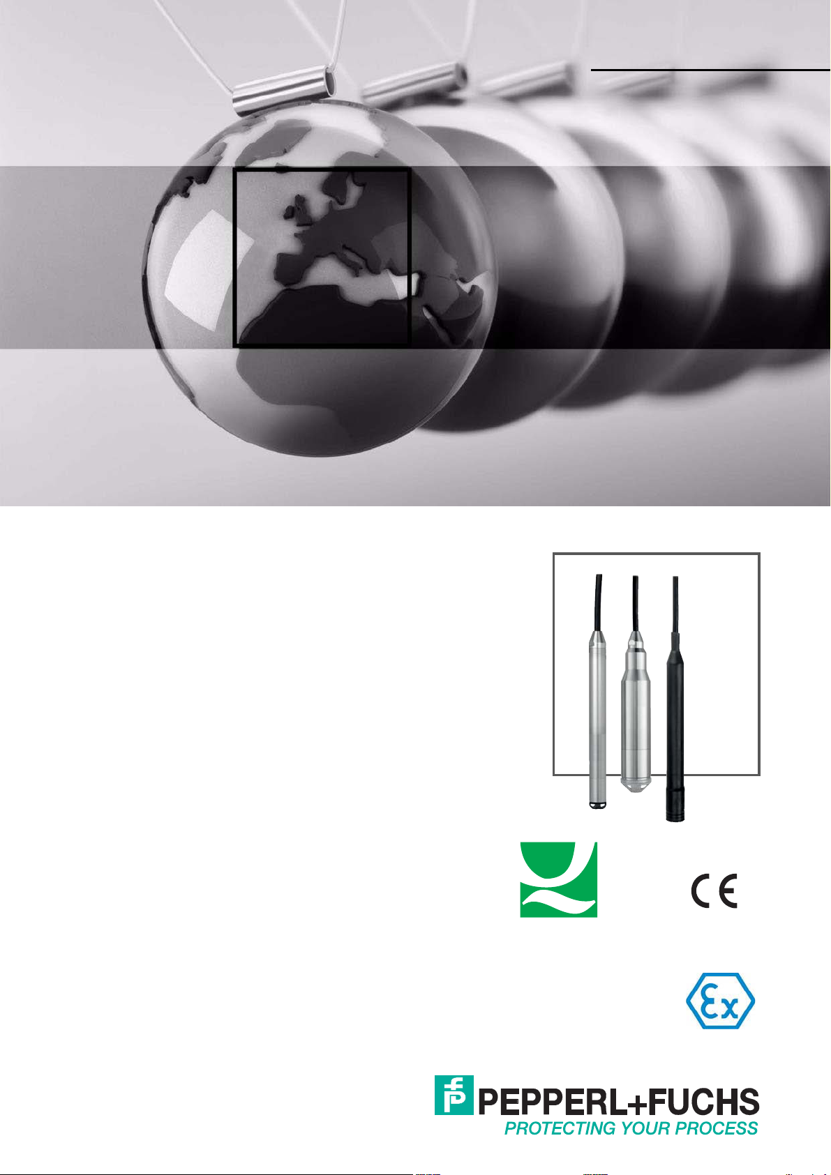
Level Probe LGC2
Hydrostatic Level
Measurement
Page 2

Level Probe LGC2
With regard to the supply of products, the current issue of the following document is applicable:
The General Terms of Delivery for Products and Services of the Electrical Industry,
published by the Central Association of the Electrical Industry (Zentralverband Elektrotechnik und
Elektroindustrie (ZVEI) e.V.) in its most recent version as well as the supplementary clause:
"Expanded reservation of proprietorship".
Application
The device is a pressure sensor for hydrostatic level measurement.
Pepperl+Fuchs offers three different versions of the device:
• Device with a stainless steel housing, external diameter of 22 mm (0.87 inch):
This version is excellently suited to drinking water applications and for use in bore holes and wells with
small diameters
• Device with a stainless steel housing, external diameter of 42 mm (1.65 inch):
Heavy-duty version and easy to clean thanks to flush-mounted process isolating diaphragm, ideally
suited to wastewater and wastewater treatment plants
• Device with plastic insulation, external diameter of 29 mm (1.14 inch):
Robust version for use in salt water and excellently suited to applications on ships (e. g. ballast water
tanks)
Your benefits
• High resistance to overload
• High-precision, robust ceramic measuring cell with long-term stability
• Climate proofed sensor thanks to completely potted electronics and 2-filter pressure compensation
system
• Simultaneous measurement of level and temperature with optionally integrated Pt100 resistance
thermometer
• Accuracy
• Standard reference accuracy ±0.2 %
• Plantinum version ±0.1 %
• Automatic density compensation to increase accuracy
• Usage in drinking water: KTW, NSF, ACS
• Approvals: ATEX, FM, CSA
• Extensive range of accessories provides complete measuring point solutions
Page 3

Level Probe LGC2
Content
1 Important Document Information . . . . . . . . . . . . . . . . . . . . . . . . . . . . . . . . . 6
1.1 Document Conventions . . . . . . . . . . . . . . . . . . . . . . . . . . . . . . . . . . . . . . 6
1.2 Terms and Abbreviations . . . . . . . . . . . . . . . . . . . . . . . . . . . . . . . . . . . . . 8
1.3 Turn down calculation . . . . . . . . . . . . . . . . . . . . . . . . . . . . . . . . . . . . . . 10
2 Function and System Design . . . . . . . . . . . . . . . . . . . . . . . . . . . . . . . . . . . . 11
2.1 Device Versions . . . . . . . . . . . . . . . . . . . . . . . . . . . . . . . . . . . . . . . . . . . . 11
2.2 Measuring Principle . . . . . . . . . . . . . . . . . . . . . . . . . . . . . . . . . . . . . . . . 13
2.3 Measuring System. . . . . . . . . . . . . . . . . . . . . . . . . . . . . . . . . . . . . . . . . . 14
2.4 Communication Protocol . . . . . . . . . . . . . . . . . . . . . . . . . . . . . . . . . . . . 16
2.5 System Integration . . . . . . . . . . . . . . . . . . . . . . . . . . . . . . . . . . . . . . . . . 16
3 Input. . . . . . . . . . . . . . . . . . . . . . . . . . . . . . . . . . . . . . . . . . . . . . . . . . . . . . . . . 17
3.1 Measured Value . . . . . . . . . . . . . . . . . . . . . . . . . . . . . . . . . . . . . . . . . . . . 17
3.2 Measuring Range. . . . . . . . . . . . . . . . . . . . . . . . . . . . . . . . . . . . . . . . . . . 17
3.3 Input Signal . . . . . . . . . . . . . . . . . . . . . . . . . . . . . . . . . . . . . . . . . . . . . . . 18
4 Output . . . . . . . . . . . . . . . . . . . . . . . . . . . . . . . . . . . . . . . . . . . . . . . . . . . . . . . 19
4.1 Output Signal . . . . . . . . . . . . . . . . . . . . . . . . . . . . . . . . . . . . . . . . . . . . . . 19
4.2 Signal Range . . . . . . . . . . . . . . . . . . . . . . . . . . . . . . . . . . . . . . . . . . . . . . 19
4.3 Maximum Load. . . . . . . . . . . . . . . . . . . . . . . . . . . . . . . . . . . . . . . . . . . . . 19
5 Supply . . . . . . . . . . . . . . . . . . . . . . . . . . . . . . . . . . . . . . . . . . . . . . . . . . . . . . . 21
5.1 Supply voltage . . . . . . . . . . . . . . . . . . . . . . . . . . . . . . . . . . . . . . . . . . . . . 21
5.2 Power Consumption . . . . . . . . . . . . . . . . . . . . . . . . . . . . . . . . . . . . . . . . 21
5.3 Current Consumption . . . . . . . . . . . . . . . . . . . . . . . . . . . . . . . . . . . . . . . 21
5.4 Connecting the Device . . . . . . . . . . . . . . . . . . . . . . . . . . . . . . . . . . . . . . 22
5.5 Terminals in the Terminal Box . . . . . . . . . . . . . . . . . . . . . . . . . . . . . . . . 24
5.6 Probe Connection (Extension Cable) . . . . . . . . . . . . . . . . . . . . . . . . . . 24
5.7 Cable Resistance. . . . . . . . . . . . . . . . . . . . . . . . . . . . . . . . . . . . . . . . . . . 24
5.8 Cable Specifications . . . . . . . . . . . . . . . . . . . . . . . . . . . . . . . . . . . . . . . . 24
5.9 Residual Ripple . . . . . . . . . . . . . . . . . . . . . . . . . . . . . . . . . . . . . . . . . . . . 24
2017-02
3
Page 4

Level Probe LGC2
Content
6 Performance Characteristics . . . . . . . . . . . . . . . . . . . . . . . . . . . . . . . . . . . . 25
6.1 Reference Conditions . . . . . . . . . . . . . . . . . . . . . . . . . . . . . . . . . . . . . . . 25
6.2 Reference Accuracy . . . . . . . . . . . . . . . . . . . . . . . . . . . . . . . . . . . . . . . . 25
6.3 Resolution . . . . . . . . . . . . . . . . . . . . . . . . . . . . . . . . . . . . . . . . . . . . . . . . 26
6.4 Long-Term Stability . . . . . . . . . . . . . . . . . . . . . . . . . . . . . . . . . . . . . . . . 26
6.5 Influence of Medium Temperature . . . . . . . . . . . . . . . . . . . . . . . . . . . . 26
6.6 Warm-up Period. . . . . . . . . . . . . . . . . . . . . . . . . . . . . . . . . . . . . . . . . . . . 26
6.7 Response Time . . . . . . . . . . . . . . . . . . . . . . . . . . . . . . . . . . . . . . . . . . . . 26
7 Installation . . . . . . . . . . . . . . . . . . . . . . . . . . . . . . . . . . . . . . . . . . . . . . . . . . . 27
7.1 Installation Instructions . . . . . . . . . . . . . . . . . . . . . . . . . . . . . . . . . . . . . 27
7.2 Additional Installation Instructions . . . . . . . . . . . . . . . . . . . . . . . . . . . 28
7.3 Cable Length . . . . . . . . . . . . . . . . . . . . . . . . . . . . . . . . . . . . . . . . . . . . . . 28
7.4 Technical Data for Cable . . . . . . . . . . . . . . . . . . . . . . . . . . . . . . . . . . . . 29
7.5 Cable Marking . . . . . . . . . . . . . . . . . . . . . . . . . . . . . . . . . . . . . . . . . . . . . 30
7.6 Cable Shortening Kit. . . . . . . . . . . . . . . . . . . . . . . . . . . . . . . . . . . . . . . . 30
8 Ambient Conditions. . . . . . . . . . . . . . . . . . . . . . . . . . . . . . . . . . . . . . . . . . . . 31
8.1 Ambient Temperature Range. . . . . . . . . . . . . . . . . . . . . . . . . . . . . . . . . 31
8.2 Storage Temperature Range . . . . . . . . . . . . . . . . . . . . . . . . . . . . . . . . . 31
8.3 Degree of Protection. . . . . . . . . . . . . . . . . . . . . . . . . . . . . . . . . . . . . . . . 32
8.4 Electromagnetic Compatibility (EMC) . . . . . . . . . . . . . . . . . . . . . . . . . 32
8.5 Surge Protection . . . . . . . . . . . . . . . . . . . . . . . . . . . . . . . . . . . . . . . . . . . 32
9 Process Conditions . . . . . . . . . . . . . . . . . . . . . . . . . . . . . . . . . . . . . . . . . . . . 33
9.1 Medium Temperature Range . . . . . . . . . . . . . . . . . . . . . . . . . . . . . . . . . 33
9.2 Medium Temperature Limit . . . . . . . . . . . . . . . . . . . . . . . . . . . . . . . . . . 33
10 Mechanical Construction . . . . . . . . . . . . . . . . . . . . . . . . . . . . . . . . . . . . . . . 34
10.1 Dimensions of the Level Probe . . . . . . . . . . . . . . . . . . . . . . . . . . . . . . . 34
10.2 Dimensions of the Suspension Clamp . . . . . . . . . . . . . . . . . . . . . . . . . 35
10.3 Dimensions of Cable Mounting Screw . . . . . . . . . . . . . . . . . . . . . . . . . 35
10.4 Dimensions of Terminal Box IP66, IP67 with Filter . . . . . . . . . . . . . . . 36
4
2017-02
Page 5

Level Probe LGC2
Content
10.5 Dimensions of the HUT Temperature Head Transmitter . . . . . . . . . . 37
10.6 Terminal Box with Integrated HUT Temperature Head Transmitter . 37
10.7 Additional Weight . . . . . . . . . . . . . . . . . . . . . . . . . . . . . . . . . . . . . . . . . . 38
10.8 Testing Adapter . . . . . . . . . . . . . . . . . . . . . . . . . . . . . . . . . . . . . . . . . . . . 38
10.9 Weight . . . . . . . . . . . . . . . . . . . . . . . . . . . . . . . . . . . . . . . . . . . . . . . . . . . . 39
10.10 Materials . . . . . . . . . . . . . . . . . . . . . . . . . . . . . . . . . . . . . . . . . . . . . . . . . . 40
11 Operation . . . . . . . . . . . . . . . . . . . . . . . . . . . . . . . . . . . . . . . . . . . . . . . . . . . . 44
12 Certificates and Approvals . . . . . . . . . . . . . . . . . . . . . . . . . . . . . . . . . . . . . . 45
12.1 CE Mark. . . . . . . . . . . . . . . . . . . . . . . . . . . . . . . . . . . . . . . . . . . . . . . . . . . 45
12.2 Approvals for hazardous area . . . . . . . . . . . . . . . . . . . . . . . . . . . . . . . . 45
12.3 Potable Water Approval . . . . . . . . . . . . . . . . . . . . . . . . . . . . . . . . . . . . . 45
12.4 Other Standards and Guidelines . . . . . . . . . . . . . . . . . . . . . . . . . . . . . . 45
12.5 Calibration . . . . . . . . . . . . . . . . . . . . . . . . . . . . . . . . . . . . . . . . . . . . . . . . 46
12.6 Calibration, Unit . . . . . . . . . . . . . . . . . . . . . . . . . . . . . . . . . . . . . . . . . . . . 46
12.7 Service . . . . . . . . . . . . . . . . . . . . . . . . . . . . . . . . . . . . . . . . . . . . . . . . . . . 46
13 Ordering Information . . . . . . . . . . . . . . . . . . . . . . . . . . . . . . . . . . . . . . . . . . . 47
13.1 Product Structure . . . . . . . . . . . . . . . . . . . . . . . . . . . . . . . . . . . . . . . . . . 47
13.2 Scope of Delivery . . . . . . . . . . . . . . . . . . . . . . . . . . . . . . . . . . . . . . . . . . 49
13.3 Configuration Data Sheet . . . . . . . . . . . . . . . . . . . . . . . . . . . . . . . . . . . . 50
14 Accessories . . . . . . . . . . . . . . . . . . . . . . . . . . . . . . . . . . . . . . . . . . . . . . . . . . 51
15 Documentation . . . . . . . . . . . . . . . . . . . . . . . . . . . . . . . . . . . . . . . . . . . . . . . . 53
15.1 Technical Information (TI) . . . . . . . . . . . . . . . . . . . . . . . . . . . . . . . . . . . 53
15.2 Brief Instructions (KA) . . . . . . . . . . . . . . . . . . . . . . . . . . . . . . . . . . . . . . 53
15.3 Manual (BA) . . . . . . . . . . . . . . . . . . . . . . . . . . . . . . . . . . . . . . . . . . . . . . . 53
15.4 Instruction Manuals (SI) . . . . . . . . . . . . . . . . . . . . . . . . . . . . . . . . . . . . . 53
15.5 Potable Water Approval . . . . . . . . . . . . . . . . . . . . . . . . . . . . . . . . . . . . . 53
16 Registered Trademarks. . . . . . . . . . . . . . . . . . . . . . . . . . . . . . . . . . . . . . . . . 54
2017-02
5
Page 6
Level Probe LGC2
Important Document Information
1 Important Document Information
1.1 Document Conventions
1.1.1 Symbols Used
This document contains symbols for the identification of warning messages and of informative
messages.
Warning Messages
You will find warning messages, whenever dangers may arise from your actions. It is
mandatory that you observe these warning messages for your personal safety and in order to
avoid property damage.
Depending on the risk level, the warning messages are displayed in descending order as
follows:
Danger!
This symbol indicates an imminent danger.
Non-observance will result in personal injury or death.
Warning!
This symbol indicates a possible fault or danger.
Non-observance may cause personal injury or serious property damage.
Caution!
This symbol indicates a possible fault.
Non-observance could interrupt the device and any connected systems and plants, or result in
their complete failure.
Informative Symbols
Note!
This symbol brings important information to your attention.
Action
This symbol indicates a paragraph with instructions. You are prompted to perform an action or
a sequence of actions.
2017-02
6
Page 7
Level Probe LGC2
)
*
Important Document Information
1.1.2 Electrical symbols
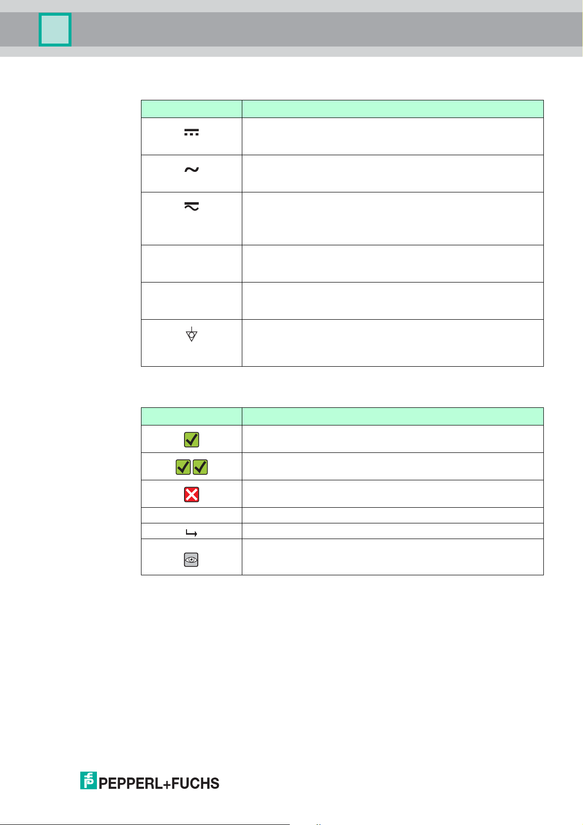
Symbol Meaning
Table 1.1
Direct current
A terminal to which DC voltage is applied or through which direct
current flows.
Alternating current
A terminal to which alternating voltage is applied or through which
alternating current flows.
Direct current and alternating current
• A terminal to which alternating voltage or DC voltage is applied.
• A terminal through which alternating current or direct current
flows.
Ground connection
A grounded terminal which, as far as the operator is concerned, is
grounded via a grounding system.
Protective ground connection
A terminal which must be connected to ground prior to establishing
any other connections.
Equipotential connection
A connection that has to be connected to the plant grounding
system: This may be a potential equalization line or a star grounding
system depending on national or company codes of practice.
1.1.3 Symbols for certain types of information
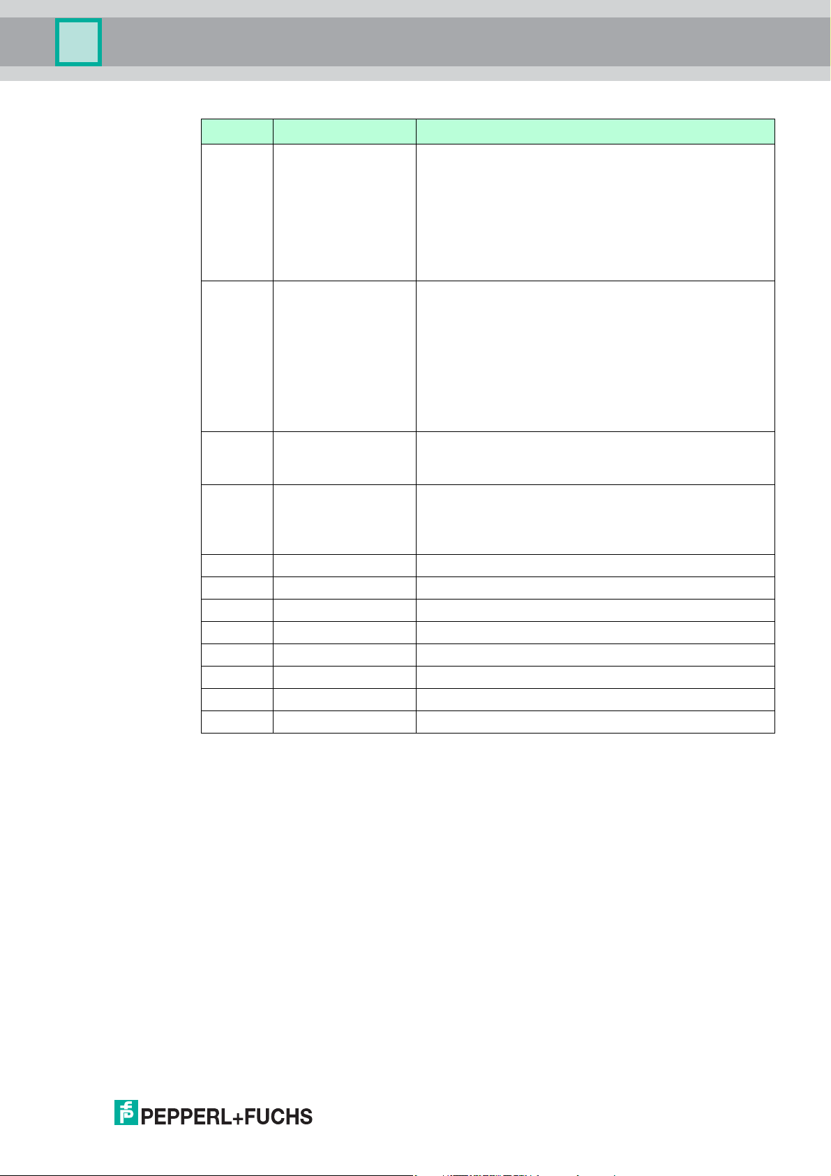
Symbol Meaning
Allowed
Indicates procedures, processes or actions that are allowed.
Preferred
Indicates procedures, processes or actions that are preferred.
Forbidden
Indicates procedures, processes or actions that are forbidden.
1., 2., 3. ... Series of steps
Result of a sequence of actions
Visual check
Table 1.2
2017-02
7
Page 8

Level Probe LGC2
URL OPLMWP
LRL
0
p
LRV
URV
1
2
3
4
Important Document Information
1.1.4 Symbols in graphics
Symbol Meaning
1, 2, 3 ... Item numbers
,…,1. 2. 3.
A, B, C, ... Views
A-A, B-B, C-C, ... Sections
-
.
Table 1.3
1.2 Terms and Abbreviations
Series of steps
Hazardous area
Indicates a hazardous area.
Safe area (non-hazardous area)
Indicates a non-hazardous location.
Figure 1.1
8
2017-02
Page 9
Level Probe LGC2
Important Document Information
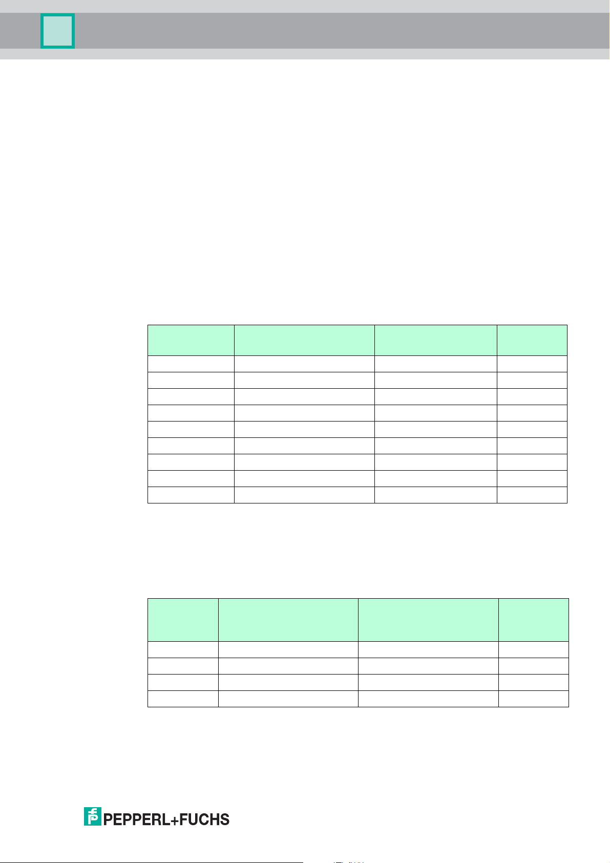
Position Terms/abbreviations Explanation
1 OPL The OPL (over pressure limit = sensor overload limit) for
2 MWP The MWP (maximum working pressure) for the sensors
3 Maximum sensor
measuring range
4 Calibrated/adjusted
span
p – Pressure
– LRL Lower range limit
– URL Upper range limit
– LRV Lower range value
– URV Upper range value
– TD (Turn down) Turn down: Example see the following section.
– PE Polyethylene
– FEP Fluorinated ethylene propylene
Table 1.4
the measuring device depends on the lowest-rated
element, with regard to pressure, of the selected
components, i. e. the process connection has to be taken
into consideration in addition to the measuring cell. Also
observe pressure-temperature dependency. For the
relevant standards and additional notes, see the
"Pressure specifications" section.
The OPL may only be applied for a limited period of time.
depends on the lowest-rated element, with regard to
pressure, of the selected components, i. e. the process
connection has to be taken into consideration in addition
to the measuring cell. Also observe pressuretemperature dependency. For the relevant standards
and additional notes, see the "Pressure specifications"
section.
The MWP may be applied at the device for an unlimited
period. The MWP can also be found on the nameplate.
Span between LRL and URL
This sensor measuring range is equivalent to the
maximum calibratable/adjustable span.
Span between LRV and URV
Factory setting: 0 to URL
Other calibrated spans can be ordered as customized
spans.
2017-02
9
Page 10

Level Probe LGC2
LRV
URLURV
LRL
1 = 2
3
Important Document Information
1.3 Turn down calculation
Figure 1.2
1 Calibrated/adjusted span
2 Zero point-based span (4 to 20 mA analog: customer-specific span can only be set at the
factory when ordered)
3 Upper range value
Example
• Sensor: 10 bar (150 psi)
• Upper range value (URL) = 10 bar (150 psi)
• Calibrated/adjusted span: 0 to 5 bar (0 to 75 psi)
• Lower range value (LRV) = 0 bar (0 psi)
• Upper range value (URV) = 5 bar (75 psi)
TD = URL/(URV – LRV)
TD = 10 bar (150 psi)/(5 bar (75 psi) – 0bar (0psi)) = 2
In this example, the TD is 2:1. This span is based on the zero point.
10
2017-02
Page 11
Level Probe LGC2
Function and System Design
2 Function and System Design
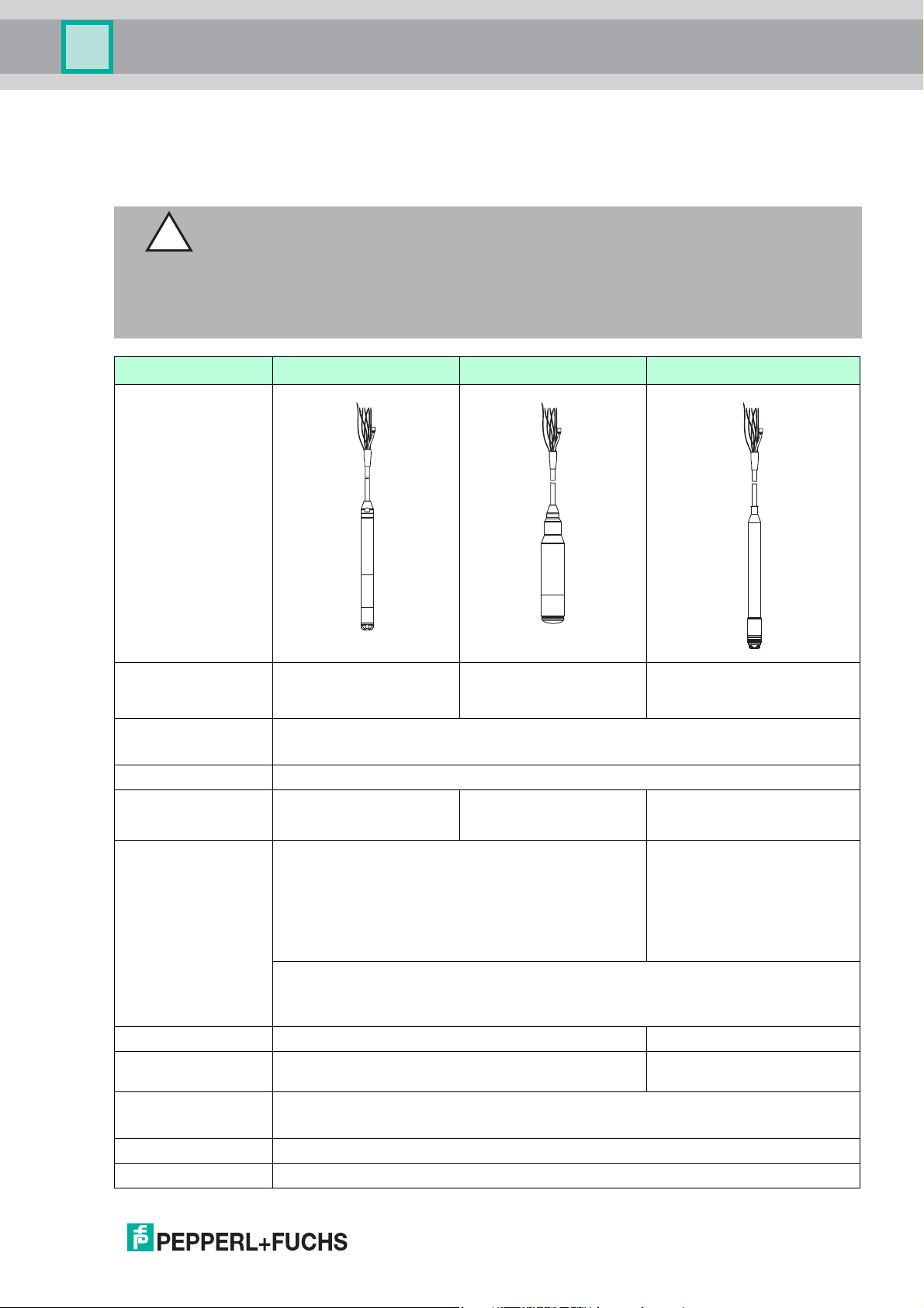
2.1 Device Versions
Caution!
Gas loss when using the device in biogas plants
The device is not suitable for use in biogas plants since the gases can diffuse through the
elastomers (seals, probe connection).
Use the devices LHCR-51, LHCS-51 for applications involving biogas.
Outer diameter 22 mm (0.87 inch) 42 mm (1.65 inch) max. 29 mm (1.14 inch)
Field of application Hydrostatic level
Process connection
(extension cable)
Probe connection PE, FEP
Seals •FKM Viton
Measuring ranges • Relative pressure: 0 to 0.1 bar (0 to 1.5 psi) to
Overload to 40 bar (600 psi) to 25 bar (375 psi)
Process temperature
range
Reference accuracy • ±0.2 % of the set span
Supply voltage 10.5 to 35 V DC, Ex: 10.5 to 30 V DC
Output 4 to 20 mA Analog
2017-02
measurement in deep
wells e. g. drinking water
• Suspension clamp
• Cable mounting screw with G1-1/2A thread or NPT1-1/2 thread
•EPDM
0 to 20 bar (0 to 300 psi)
• Absolute pressure: 0 to 2 bar (0 to 30 psi) to
0 to 20 bar (0 to 300 psi)
• Customer-specific measuring ranges; factory-calibrated.
• The following output units can be configured: %, mbar, bar, kPa, MPa, mm H2O,
m H2O, inch H2O, foot H2O, psi and numerous level units.
-10 to +70 °C (+14 to +158 °F) 0 to +50 °C (+32 to +122 °F)
• optional: ±0.1 % of the set span (Platinum version)
1
Hydrostatic level
measurement in
wastewater
FKM Viton •FKM Viton
Hydrostatic level
measurement in saltwater
•EPDM
• Relative pressure:
0 to 0.1 bar (0 to 1.5 psi)
to 0 to 4 bar (0 to 60 psi)
• Absolute pressure:
0 to 2 bar (0 to 30 psi) to
0 to 4 bar (0 to 60 psi)
1
11
Page 12

Level Probe LGC2
Function and System Design
Outer diameter 22 mm (0.87 inch) 42 mm (1.65 inch) max. 29 mm (1.14 inch)
Options Drinking water approval –
• Wide range of approvals, including ATEX, FM, CSA
• Numerous accessories
• Integrated Pt100 resistance thermometer and HUT temperature head transmitter
(4 to 20 mA)
Specialties • High-precision, robust ceramic measuring cell with long-term stability
• Automatic density compensation
• Customer-specific cable marking
1
Recommended for drinking water applications, not suitable for use in hazardous areas.
12
2017-02
Page 13
Level Probe LGC2
.
.
2
1
ρ x g
h ~ p
h =
p
p
hydr
p
atm
p
atm
p = p +
atm hydr.
p
h
p = p + p
atm hydr
p
atm
Rel.: p = (p + p ) -
sens atm hydr.
Abs.: p = (p +
sens atm hydr.
p)
p
atm
Function and System Design
2.2 Measuring Principle
The ceramic measuring cell is a dry measuring cell i. e. the pressure acts directly on the robust,
ceramic process isolating diaphragm of the device. Changes in air pressure are guided via a
pressure compensation tube through the extension cable to the rear of the ceramic process
isolating diaphragm and are compensated for. A pressure-dependent change in capacitance,
caused by the movement of the process isolating diaphragm, is measured at the electrodes of
the ceramic carrier. The electronics unit then converts this to a signal that is proportional to the
pressure and linear to the level.
Figure 2.1
1 Ceramic measuring cell
2 Pressure compensation tube
h Height level
p Total pressure = atmospheric pressure + hydrostatic pressure
r Density of the medium
g Acceleration due to gravity
P
hydr.
P
atm
P
sens
Temperature measurement with optional Pt100 resistance
thermometer
For simultaneous measurement of level and temperature, Pepperl+Fuchs offers the device
with an optional 4-wire Pt100 resistance thermometer. The Pt100 ressistance thermometer is
categorized as Accuracy Class B as per DIN/EN 60751.
Hydrostatic pressure
Atmospheric pressure
Pressure displayed on the sensor
1
2017-02
1
Not for use in hazardous areas.
13
Page 14
Level Probe LGC2
ON
1
2
E
-+-
%
Function and System Design
Temperature measurement with optional Pt100 resistance thermometer
and HUT temperature head transmitter
To convert the temperature signal to an analog, scalable 4 to 20 mA output signal,
Pepperl+Fuchs also offers the HUT temperature head transmitter. Ordering information:
product structure, feature "Accessories", option "XP".
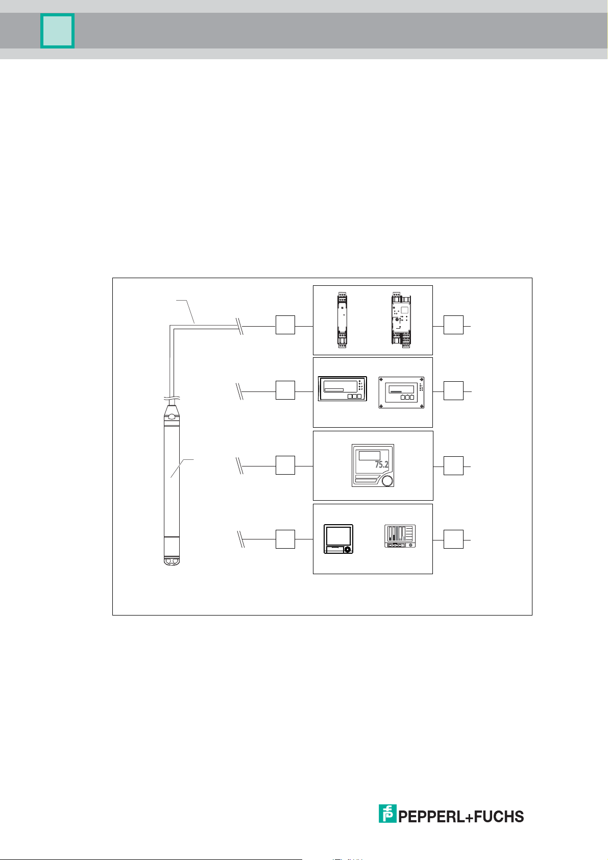
2.3 Measuring System
Application Examples
As standard, the complete measuring system consists of a level probe and a transmitter power
supply unit with a supply voltage of 10.5 to 30 V DC (hazardous areas) or 10.5 to 35 V DC
(non-hazardous areas).
Possible measuring point solutions with a signal converter and evaluation device:
2
1
A
3
3
2
1
5
6
4
KFD2-CR4-1
PWR
9107
12
11
13 15
14
B
ON
3
132465
KFD2-CRG2-
1.D
PWR
FLT
12
OUT
RS232
9137
8
15
14
19 21
20
12401.5
ESC
OK
121610
11
18
17
22 24
23
E
-+-
4
5
ON
1
2
4
5
C
1
3
4
5
D
4
5
Figure 2.2
3
1 Level probe LGC
2 4to20mA
3 and 4 Surge protection device, e. g. for DIN mounting rail mounting, selection in accordance
with supply voltage, not for use in hazardous areas
5 Power supply
14
1
Not for use in hazardous areas.
2017-02
Page 15
Level Probe LGC2
E
F
2
3
4
3
4
5
5
5
6
6
6
7
7
7
1
2
5
12401.5
E
-+-
ON
1
2
ON
1
2
E
-+-
ON
1
2
E
-+-
ONON
1
2
E
-+-
ONON
1
2
E
-+-
%
ESC
OK
KFD2-CRG2-
1.D
RS232
PWR
12
FLT
OUT
19 21
15
9137
20
14
8
22 24
18
121610
23
17
11
132465
ESC
OK
KFD2-CRG2-
1.D
RS232
PWR
12
FLT
OUT
19 21
15
9137
20
14
8
22 24
18
121610
23
17
11
132465
Function and System Design
A: Easy and cost-effective measuring point solution: power supplied to the device in
hazardous and non-hazardous areas via a transmitter power supply. Power supply and
additional control of two appliances, such as pumps, via a trip amplifier with local display.
B: An evaluation device offers power supply, local display and two switch outputs.
C: If several pumps are used, the pump service life can be prolonged by alternate switching.
With alternating pump control, the pump which was out of service for the longest period of time
is switched on. Use a suitable evaluation device for this application.
D: State-of-the-art recording technology with graphic display recorders for documentation,
monitoring, visualization and archiving purposes.
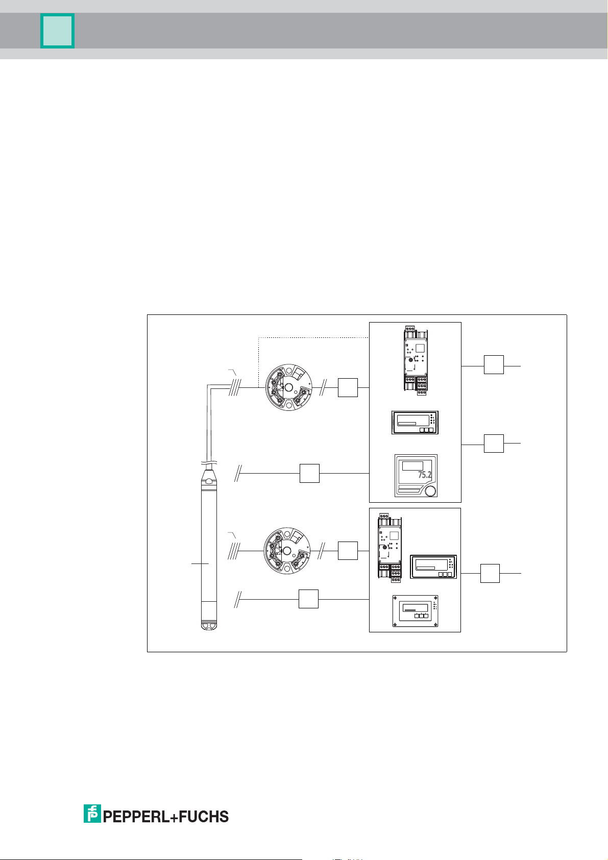
Application Examples with the Pt100 Resistance Thermometer
As standard, the complete measuring system consists of a level probe and a transmitter power
supply unit with a supply voltage of 10.5 to 30 V DC (hazardous areas) or 10.5 to 35 V DC
(non-hazardous areas).
Possible measuring point solutions with a signal converter and evaluation device:
Figure 2.3
2017-02
15
Page 16

Level Probe LGC2
Function and System Design
1 Level probe LGC
2 Connection for integrated Pt100 in the device
3 Temperature for 4 to 20 mA
4 Level for 4 to 20 mA
5 Surge protection device, e. g. on the sensor side for field installation: for DIN mounting
rail mounting, selection in accordance with supply voltage, not for use in hazardous areas
6 Surge protection device, e. g. for DIN mounting rail mounting, selection in accordance
with supply voltage, not for use in hazardous areas
7 Power supply
E: If you wish to measure, display and evaluate the temperature as well as the level, e. g. to
monitor the temperature in fresh water for the purpose of detecting temperature limits for germ
formation, the options available to you include the following: The optionally available HUT
temperature head transmitter can convert the Pt100 signal into a 4 to 20 mA signal and
transfer it to any commonly used evaluation device. Some evaluation devices also offer a
direct input for the Pt100 signal.
F: If you wish to record and evaluate the level and temperature measured value with one
device, use evaluation devices with two inputs. It is even possible to mathematically link the
input signals with this unit.
2.4 Communication Protocol
4to20mA Analog
Ordering information: product structure, feature "Electrical output", option "I2"
2.5 System Integration
The device can be given a tag name.
Ordering information: product structure, feature "Marking", option "1Z"
16
2017-02
Page 17
Level Probe LGC2
Input
3Input
3.1 Measured Value
Level probe and Pt100 (optional)
• Hydrostatic pressure of a liquid
• Pt100: temperature
HUT temperature head transmitter (optional) for device with
4 to 20 mA Analog
Temperature
3.2 Measuring Range
• Customer-specific measuring ranges or calibration that has been preset in the factory
• Temperature measurement of -10 to +70 °C(+14to+158°F) with Pt100 (optional)
Relative pressure
Measuring range
[bar (psi)]
0.1 (1.5) 0.01 (0.15) 0.3 (4.5) R1A
0.2 (3.0) 0.02 (0.3) 0.3 (4.5) R1C
0.4 (6.0) 0.04 (1.0) 0 R1D
0.6 (9.0) 0.06 (1.0) 0 R1E
1.0 (15.0) 0.1 (1.5) 0 R2A
2.0 (30.0) 0.2 (3.0) 0 R2C
4.0 (60.0) 0.4 (6.0) 0 R2D
10.0 (150)
20.0 (300)
Table 3.1
3
3
Lowest calibratable span
[bar (psi)]
1.0 (15) 0 R3A
2.0 (30) 0 R3C
1
Vacuum resistance
[bar
abs
(psi
abs
Option
2
)]
1
Largest turn down that can be configured at the factory: 10:1, higher turn down can be configured on request.
2
See ordering information: product structure, feature "Measuring range".
3
These measuring ranges are not available for the special version with plastic insulation, external diameter of
29 mm (1.14 inch).
Absolute pressure
Measuring
range
Lowest calibratable span
[bar (psi)]
1
Vacuum resistance
[bar
abs
(psi
abs
)]
[bar (psi)]
2.0 (30.0) 0.2 (3.0) 0 A2C
4.0 (60.0) 0.4 (6.0) 0 A2D
10.0 (150)
20.0 (300)
Table 3.2
1
Largest turn down that can be configured at the factory: 10:1, higher turn down can be configured on request.
2
See ordering information: product structure, feature "Measuring range".
3
These measuring ranges are not available for the special version with plastic insulation, external diameter of
29 mm (1.14 inch).
2017-02
3
1.0 (15) 0 A3A
3
2.0 (30) 0 A5A
Option
2
17
Page 18

Level Probe LGC2
Input
3.3 Input Signal
Level probe and Pt100 (optional)
• Change in capacitance
• Pt100: change in resistance
HUT temperature head transmitter (optional) for device with
4...20mAAnalog
Pt100 resistance signal, 4-wire
18
2017-02
Page 19

Level Probe LGC2
413
630
195
1065
35
20
255
15
847
30
3020 25158
35
10
1080
880
480
280
680
80
R
Lmax
–2x0.09
xL–R
U–10.5 V
23 mA
m
–
R
U
–
8 V
0.025 A
R
Lmax
add
add
10.
R
[]
U
[ ]
V
A
B
R
[]
U
[]
V
Output
4Output
4.1 Output Signal
Level probe and Pt100 (optional)
• 4 to 20 mA Analog, 2-wire for hydrostatic pressure measured value.
Ordering information: product structure, feature "Electrical output", option "I2".
• Pt100: temperature-dependent resistance value
HUT temperature head transmitter (optional) for device with
4 to 20 mA Analog
4 to 20 mA Analog for temperature measured value, 2-wire
4.2 Signal Range
3.8 to 20.5 mA
4.3 Maximum Load
The maximum load resistance depends on the supply voltage (U) and must be determined
individually for each current loop, see formula and diagrams for device and temperature head
transmitter. The total resistance resulting from the resistances of the connected devices, the
connecting cable and, where applicable, the resistance of the probe connection may not
exceed the load resistance value.
Figure 4.1
A Load diagram of the device for estimating the load resistance. Additional resistances,
such as the resistance of the extension cable, have to be subtracted from the value
calculated as shown in the equation.
B Load diagram for HUT temperature head transmitter for estimating the load
resistance. Additional resistances must be subtracted from the value calculated as
R
Lmax
R
add
shown in the equation.
Max. load resistance []
Additional resistances such as resistance of evaluating device and/or display unit,
cable resistance []
U Supply voltage [V]
L Basic length of probe connection [m] (cable resistance per wire 0.09 /m)
2017-02
19
Page 20

Level Probe LGC2
Output
Note!
When using the measuring device in hazardous areas, installation must comply with the
corresponding national standards and regulations and the instruction manuals or installation or
control drawings (SI, ZD).
20
2017-02
Page 21

Level Probe LGC2
Supply
5Supply
Warning!
Danger to life from wrong connection of the device
The electrical safety of the device is not guaranteed.
When using the measuring device in a hazardous area, the relevant national standards and
guidelines as well as the instruction manuals (SI) or installation or control drawings (ZD) must
be adhered to. All data relating to explosion protection can be found in separate
documentation which is available on request. This documentation is supplied with the devices
as standard, see chapter 15.
5.1 Supply voltage
Level probe and Pt100 (optional)
• 10.5to35VDC (non-hazardous areas)
• 10.5to30VDC (hazardous areas)
HUT temperature head transmitter (optional) for device with
4 to 20 mA Analog
8to35VDC
5.2 Power Consumption
Level probe and Pt100 (optional)
• 0.805 W at 35 V DC (non-hazardous areas)
• 0.690 W at 30 V DC (hazardous areas)
HUT temperature head transmitter (optional) for device with
4 to 20 mA Analog
0.875 W at 35 V DC
5.3 Current Consumption
Level probe and Pt100 (optional)
• Max.current consumption: 23 mA
• Min. current consumption: 3.6 mA
HUT temperature head transmitter (optional) for device with
4 to 20 mA Analog
• Max. current consumption: 25 mA
• Min. current consumption: 3.5 mA
2017-02
21
Page 22

Level Probe LGC2
Supply
5.4 Connecting the Device
•Device
Reverse polarity protection is integrated into the device and the temperature head
transmitter. Changing the polarities will not result in damage to the devices.
• The cable must end in a dry room or a suitable terminal box. The terminal box (IP66/IP67)
with GORETEX
®
filter from Pepperl+Fuchs is suitable for outdoor installation. The terminal
box may be ordered as an accessory using the order code for the device, ordering
information: product structure, feature "Accessories", option "SP".
The electrical connection is made with the corresponding wires of the probe cable and with the
optional use of the terminal box and a power supply (e. g. transmitter power supply (see
chapter 2.3)).
Level probe and Pt100
AB
)
a
)
RD
BK
LGC
b
c
d
)
a
)
BK
RD
WH
LGC
b
c
d
YE BU
BR
e
Figure 5.1
A Level probe LGC
B Level probe and Pt100 resistance thermometer (not for use in hazardous areas), ordering
information, feature "Accessories", option "BN"
a Not for the level probe with external diameter of 29 mm (1.14 inch)
b 10.5 to 30 V DC (hazardous area), 10.5 to 35 V DC
c 4to20mA
d Resistance (R
)
L
e Pt100 resistance thermometer
22
2017-02
Page 23

Level Probe LGC2
RD BKWHYE
BU
BR
)
)
a
b
c
f
d
cd
g
6
5
4
3
2
1
e
LGC 4 ... 20 mA Analog
Supply
Level probe with Pt100 and HUT temperature head transmitter for device
with 4to20mAAnalog
Figure 5.2
a Not for the level probe with external diameter of 29 mm (1.14 inch)
b 10.5to35VDC
c 4to20mA
d Resistance (R
)
L
e Temperature head transmitter HUT (4 to 20 mA) (not for use in hazardous area)
f 8to35VDC
g Pt100 resistance thermometer
1to6 Terminal assignment
Ordering information:
Pt100 resistance thermometer: product structure, feature "Accessories", option "BN".
HUT temperature head transmitter: product structure, feature "Accessories", option "XP"
Wire colors
RD = red, BK = black, WH = white, YE = yellow, BU = blue, BR = brown
Connection data
Connection classification as per IEC 61010-1:
• Overvoltage category 1
• Pollution level 1
Connection data in the hazardous area
See relevant instruction manuals (SI, ZD).
2017-02
23
Page 24

Level Probe LGC2
Supply
5.5 Terminals in the Terminal Box
• Three terminals as standard in the terminal box. The terminal box can optionally be
ordered as an accessory.
• 4-terminal strip can be ordered as an accessory, cable cross section 0.08 to 2.5 mm
(28to14AWG)
Note!
The 4-terminal strip is not designed for use in hazardous areas incl. CSA General Purpose.
5.6 Probe Connection (Extension Cable)
• Overall external diameter: 8 mm (0.31 inch) ±0.25 mm (0.01 inch)
• Pressure compensation tube with PTFE filter: external diameter 2.5 mm (0.1 inch), internal
diameter 1.5 mm (0.06 inch)
Cross section
• Device: 3 x 0.2 mm2 (3 x 26 AWG) and pressure compensation tube with PTFE filter
• Level probe and Pt100 (optional): 7 x 0.2 mm
tube with PTFE filter
2
(7 x 26 AWG) and pressure compensation
2
5.7 Cable Resistance
per wire: 0.09 /m
5.8 Cable Specifications
Pepperl+Fuchs recommends using shielded, twisted-pair two-wire cables.
Note!
The probe cables are shielded for device versions with outer diameters of 22 mm (0.87 inch)
and 42 mm (1.65 inch).
Level probe and Pt100 (optional)
• Commercially available instrument cable
• Terminals, terminal box: 0.08 to 2.5 mm
HUT temperature head transmitter (optional) for device with
4 to 20 mA Analog
• Commercially available instrument cable
• Terminals, terminal box: 0.08 to 2.5 mm
• Transmitter connection: max. 1.75 mm
5.9 Residual Ripple
2
(28to14AWG)
2
(28to14AWG)
2
(15 AWG)
24
Level probe and Pt100 (optional)
No impact on the 4 to 20 mA signal up to ±5 % residual ripple within the permitted voltage
range.
HUT temperature head transmitter (optional)
Uss 5V at U 13 V, f
max.
=1kHz
2017-02
Page 25

Level Probe LGC2
Performance Characteristics
6 Performance Characteristics
6.1 Reference Conditions
Level probe and Pt100 (optional)
• As per IEC 60770
• Ambient temperature T
• Humidity = constant, in the range: 20 to 80 % r.F
•Ambient pressure p
• Position of measuring cell constant, vertical in the range ±1°
• Supply voltage constant: 21 V DC to 27 V DC
• Pt100: DIN EN 60770, T
HUT temperature head transmitter (optional) for device with
4 to 20 mA Analog
Calibration temperature +23 °C(+73°F) ±5K
= constant, in the range: +21 to +33 °C(+70to+91°F)
amb
= constant, in the range: 860 to 1060 mbar (12.47 to 15.37 psi)
amb
= +25 °C(+77°F)
amb
6.2 Reference Accuracy
Level probe and Pt100 (optional)
The reference accuracy comprises the non-linearity after limit point configuration, hysteresis
and non-reproducibility in accordance IEC 60770.
1
Standard version
Setting ±0.2 %
• to TD 5:1: < 0.2 % of set span
• from TD 5:1 to TD 20:1: ±(0.02 x TD + 0.1)
Platinum version
Setting ±0.1 % (optional)
• to TD 5:1: < 0.1 % of set span
• from TD 5:1 to TD 20:1: ±(0.02 x TD)
Class B as per DIN EN 60751
Pt100: max. ±1K
HUT temperature head transmitter (optional) for device with
4 to 20 mA Analog
• ±0.2 K
• With Pt100: max. ±0.9 K
:
2
:
1
Ordering information: product structure, feature "Reference accuracy", option "G".
2
2017-02
Ordering information: product structure, feature "Reference accuracy", option "D".
25
Page 26

Level Probe LGC2
Performance Characteristics
6.3 Resolution
Current output: 1 A
6.4 Long-Term Stability
Level probe and Pt100 (optional)
• 0.1 % of URL/year
• 0.25 % of URL/5 years
HUT temperature head transmitter (optional) for device with
4 to 20 mA Analog
0.1 K per year
6.5 Influence of Medium Temperature
• Thermal change in the zero output and the output span:
0to+30°C (+32 to +86 °F): <(0.15+0.15xTD)% of set span
-10 to +70 °C (+14 to +158 °F): < (0.4 + 0.4 x TD) % of set span
• Temperature coefficient (T
-10 to +70 °C (+14 to +158 °F): 0.1%/10K of URL
) of the zero output and the output span
K
6.6 Warm-up Period
Level probe and Pt100 (optional)
• Device: < 6 s
• Pt100: 20 m
HUT temperature head transmitter (optional) for device with
4 to 20 mA Analog
4s
6.7 Response Time
Level probe and Pt100 (optional)
• Device: 400 ms (T90 time), 500 ms (T99 time)
• Pt100: 160 s (T90 time), 300 s (T99 time)
26
2017-02
Page 27

Level Probe LGC2
-
OPEN
CLOSE
90°
90°
1
2
3
4
5
6
7
8
9
Installation
7Installation
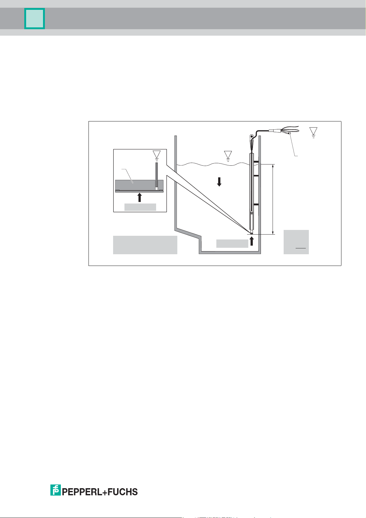
7.1 Installation Instructions
Figure 7.1
1 Cable mounting screw can be ordered as an accessory
2 Terminal box can be ordered as an accessory
3 Bending radius of extension cable > 120 mm (4.72 inch)
4 Mounting clamp can be ordered as an accessory
5 Probe connection (extension cable), cable length
6 Guide tube
7 Level probe LGC
8 Additional weight can ordered be an accessory for the level probe with external diameter
of 22 mm (0.87 inch) and 29 mm (1.14 inch)
9 Protection cap
2017-02
27
Page 28

Level Probe LGC2
Installation
7.2 Additional Installation Instructions
• Sideways movement of the level probe can result in measuring errors. For this reason,
install the probe at a point free from flow and turbulence, or use a guide tube. The internal
diameter of the guide tube should be at least 1 mm (0.04 inch) greater than the external
diameter of the selected device.
• To avoid mechanical damage to the measuring cell, the device is equipped with a
protection cap.
• The cable must end in a dry room or a suitable terminal box. The terminal box from
Pepperl+Fuchs provides humidity and climatic protection and is suitable for installation
outdoors, see chapter 14.
• Cable length tolerance: < 5 m (16 foot): ±17.5 mm (0.69 inch); > 5 m (16 foot): ±0.2 %
• If the cable is shortened, the filter at the pressure compensation tube must be reattached.
Pepperl+Fuchs offers a cable shortening kit for this purpose, see chapter 14.
• Pepperl+Fuchs recommends using twisted, shielded cable.
• In shipbuilding applications, measures are required to restrict the spread of fire along cable
looms.
• The length of the extension cable depends on the intended level zero point. The height of
the protection cap must be taken into consideration when designing the layout of the
measuring point. The level zero point (E) corresponds to the position of the process
isolating diaphragm. Level zero point = E; tip of probe = L (see the following diagram).
For dimensions, see chapter 10.
Figure 7.2
7.3 Cable Length
• Pay attention to the load.
• Cable lengths available for order
• Customer-specific in meters or feet.
• Limited cable length when performing installation with freely suspended device with
cable mounting screw or mounting clamp, as well as for Ex approval: max. 300 m
(984 foot).
Note!
When using the measuring device in hazardous areas, installation must comply with the
corresponding national standards and regulations and the instruction manuals (SI) or
Installation or Control Drawings (ZD).
E
L
28
2017-02
Page 29

Level Probe LGC2
A
Installation
Figure 7.3
A Length of probe connection (extension cable)
1
Option
Probe connection (extension cable)
2A 10 m cable, shortable, PE
2C 20 m cable, shortable, PE
2M 30 foot cable, shortable, PE
2N 60 foot cable, shortable, PE
3A 10 m cable, shortable, FEP
3C 20 m cable, shortable, FEP
3M 30 foot cable, shortable, FEP
3N 60 foot cable, shortable, FEP
CF Specification in foot cable, shortable, FEP
CM Specification in m cable, shortable, FEP
XF Specification in foot cable, shortable, PE
XM Specification in m cable, shortable, PE
Table 7.1
1
Ordering information: product structure, feature "Probe connection"
7.4 Technical Data for Cable
• Minimum bending radius: 120 mm (4.72 inch)
• Tensile strength: max. 950 N (213.56 lbf)
• Cable extraction force (= tensile force required to extract the cable from the probe):
•PE, FEP: typically 400 N (89.92 lbf)
• when used in hazardous area: 100 N (73.75 lbf)
• UV-resistant (UV = ultraviolet)
• PE: for use in drinking water
2017-02
29
Page 30

Level Probe LGC2
Installation
7.5 Cable Marking
Figure 7.4
• To make installation easier, Pepperl+Fuchs marks the extension cable if a customerspecific length has been ordered.
Ordering information: product structure, feature "Service", option "RI" or "SI".
• Cable marking tolerance (distance to lower end of level probe):
Cable length < 5 m (16 foot): ±17.5 mm (0.69 inch)
Cable length > 5 m (16 foot): ±0.2 %
• Material: PET, stick-on label: acrylic
• Immunity to temperature change: -30 to +100 °C(-22to+212°F)
Note!
The marking is used exclusively for installation purposes. The mark must be thoroughly
removed without trace in the case of devices with drinking water approval. The extension cable
must not be damaged in the process.
Not for use of the device in hazardous areas.
7.6 Cable Shortening Kit
30
Figure 7.5
The cable shortening kit is used to shorten a cable easily and professionally.
Note!
The cable shortening kit is not designed for the device with FM/CSA approval.
Ordering information: product structure, feature "Accessories", option "WP"
2017-02
Page 31

Level Probe LGC2
Ambient Conditions
8 Ambient Conditions
8.1 Ambient Temperature Range
Level probe and Pt100 (optional)
• With external diameter of 22 mm (0.87 inch) and 42 mm (1.65 inch):
-10 to +70 °C(+14to+158°F) (= medium temperature)
• With external diameter of 29 mm (1.14 inch):
0to+50°C(+32to+122°F) (= medium temperature)
Probe connection (extension cable)
(when mounted in a fixed position)
•With PE: -30to+70°C (-22 to +158 °F)
•With FEP: -40to+70°C(-40to+158°F)
Te rm i n a l bo x
-40 to +80 °C(-40to+176°F)
HUT temperature head transmitter (optional) for device with
4 to 20 mA Analog
-40 to +85 °C(-40to+185°F)
Temperature head transmitter 2-wire, configured for a measuring range of -20 to +80 °C
(-4 to +176 °F). This configuration offers a temperature range of 100 K which can be easily
mapped. Please note that the Pt100 resistance thermometer is suitable for a temperature
range of -10 to +70 °C (14 to +158 °F).
Note!
The temperature head transmitter is not designed for use in hazardous areas incl. CSA
General Purpose.
8.2 Storage Temperature Range
Level probe and Pt100 (optional)
-40 to +80 °C(-40to+176°F)
Probe connection (extension cable)
(when mounted in a fixed position)
•With PE: -30to+70°C(-22to+158°F)
•With FEP: -30to+80°C(-22to+176°F)
Te rm i n a l bo x
-40 to +80 °C(-40to+176°F)
HUT temperature head transmitter (optional) for device with
4 to 20 mA Analog
-40 to +100 °C (-40 to +212 °F)
2017-02
31
Page 32

Level Probe LGC2
Ambient Conditions
8.3 Degree of Protection
Level probe and Pt100 (optional)
IP68, permanently hermetically sealed at 20 bar (290 psi) (~200 m H2O)
Terminal box (optional)
IP66, IP67
HUT temperature head transmitter (optional) for device with
4 to 20 mA Analog
IP00, condensation permitted
When installed in the optional terminal boxes: IP66/IP67
8.4 Electromagnetic Compatibility (EMC)
Level probe and Pt100 (optional)
• EMC in accordance with all relevant requirements of EN 61326 series. For details, refer to
the Declaration of Conformity.
• Maximum deviation: < 0.5 % of span.
HUT temperature head transmitter (optional) for device with
4 to 20 mA Analog
Interference emission to EN 61326 Class B equipment, interference immunity to EN 61326
Appendix A (Industrial). For details, refer to the Declaration of Conformity.
8.5 Surge Protection
Level probe and Pt100 (optional)
• Integrated overvoltage protection as per EN 61000-4-5 (500 V symmetrical/1000 V
asymmetrical)
• Overvoltage protection 1.0 kV, external if necessary
HUT temperature head transmitter (optional) for device with
4 to 20 mA Analog
Provide overvoltage protection, externally if necessary, see chapter 2.3.
32
2017-02
Page 33

Level Probe LGC2
Process Conditions
9 Process Conditions
9.1 Medium Temperature Range
Level probe and Pt100 (optional)
• With external diameter of 22 mm (0.87 inch) and 42 mm (1.65 inch):
-10 to +70 °C(+14to+158°F)
• With external diameter of 29 mm (1.14 inch):
0to+50°C(+32to+122°F)
HUT temperature head transmitter (optional) for device with
4 to 20 mA Analog
-40 to +85 °C (-40 to +185 °F) (= ambient temperature), install temperature head transmitter
outside the medium.
Temperature head transmitter 2-wire, configured for a measuring range of -20 to +80 °C
(-4 to +176 °F). This configuration offers a temperature range of 100 K which can be easily
mapped. Please note that the Pt100 resistance thermometer is suitable for a temperature
range of -10 to +70 °C (14 to +158 °F).
Note!
The temperature head transmitter is not designed for use in hazardous areas incl. CSA
General Purpose.
9.2 Medium Temperature Limit
Level probe and Pt100 (optional)
With external diameter of 22 mm (0.87 inch) and 42 mm (1.65 inch): -20 to +70 °C
(-4 to +158 °F)
Note!
In hazardous area incl. CSA General Purpose, the medium temperature limit is
-10 to +70 °C(+14to+158°F).
With external diameter of 29 mm (1.14 inch): 0 to +50 °C(+32to+122°F)
Note!
The device may be operated in this temperature range. The specification values, such as
accuracy, may be exceeded.
2017-02
33
Page 34

Level Probe LGC2
Mechanical Construction
10 Mechanical Construction
10.1 Dimensions of the Level Probe
ABC
1
2
Ø8(0.31)
Ø8(0.31)
(9.13)
±0.1
(9.72)
232
247
249 (9.80)
259 (10.2)
18 (0.71)
33 3
Ø22 (0.87)
1
2
18 (0.71)
Ø42 (1.65)
Ø42.5 (1.67)
Ø8(0.31)
(10.2)
(10.6)
258
268
1
2
27 (1.06)
Ø29≤(1.14)
34
Figure 10.1
A Ordering information: product structure, feature "Probe tube", option "S" or "Accessories"
B Ordering information: product structure, feature "Probe tube", option "R"
C Ordering information: product structure, feature "Probe tube", option "P"
1 Pressure compensation tube
2 Probe connection (extension cable)
3 Protection cap
Measuring unit mm (inch)
2017-02
Page 35

Level Probe LGC2
22 (0.87)
48... 52 (2.0)
≤
175 (6.89)
52 (2.05)
~53
(2.1)
~71 (2.8)
Ø55(2.17)
~71 (2.8)
NPT
36
41
G1-1/2A
1-1/2
A
B
Mechanical Construction
10.2 Dimensions of the Suspension Clamp
Figure 10.2
Ordering information: product structure, feature "Accessories", option "OP"
Measuring unit mm (inch)
10.3 Dimensions of Cable Mounting Screw
Figure 10.3
A G1-1/2A, ordering information: product structure, feature "Accessories", option "PQ"
B NPT1-1/2, ordering information: product structure, feature "Accessories", option "PR"
Measuring unit mm (inch)
Note!
Use only in unpressurized vessels.
2017-02
35
Page 36

Level Probe LGC2
55 (2.17)
120 (4.72)
60 (2.36)
0.5±
10 (0.39)
80 (3.15)
~30
(1.18)
Ø4.5 (0.18)
50.2
(1.98)
108.2 (4.26)
OPEN
CLOSE
90°
90°
Warning:
Avoid electrostatic charge in explosive atmosphere.
See instructions
Ter mi nal Bo x
5
3
4
2
1
Mechanical Construction
10.4 Dimensions of Terminal Box IP66, IP67 with Filter
Figure 10.4
1 Stopping plug M20 x 1.5
2 Cable gland M20 x 1.5
3
4 to 20 mA; terminals for 0.08 to 2.5 mm (28 to 14 AWG) 0.08 to 2.5 mm
4
Ground connection; terminals for 0.08 to 2.5 mm (28 to 14 AWG) 0.08 to 2.5 mm
5
GORE-TEX
®
filter
2
2
Measuring unit mm (inch)
Terminal box IP66/IP67 with GORE-TEX® filter incl. 3 installed terminals. The terminal box is
also suitable for the installation of a temperature head transmitter or four other terminals.
Ordering information:
• Terminal box: product structure, feature "Accessories", option "SP", see chapter 14
• HUT temperature head transmitter: product structure, feature "Accessories", option "XP",
see chapter 14
Note!
The terminal box is not designed for the device with type of protection Ex nA in hazardous
areas. If the terminal box is used in a hazardous area, the Safety Instructions of the relevant
device must be observed, as well as the applicable regulations for explosion protection.
If the device with optional Pt100 is supplied, a terminal block is provided with the terminal box
for the purpose of wiring the Pt100.
36
Note!
The 4-terminal block is not designed for use in hazardous areas incl. CSA General Purpose.
2017-02
Page 37

Level Probe LGC2
Ø5(Ø0.19)
33 (1.30)
Ø44 (1.73)
Ø7 (0.27)
21 (0.83)
3
4
5
3
6
1
2
> 7 (0.28)12 3
Mechanical Construction
10.5 Dimensions of the HUT Temperature Head Transmitter
Figure 10.5
Measurement unit mm (inch)
Ordering information: product structure, feature "Accessories", option "XP", see chapter 14
10.6 Terminal Box with Integrated HUT Temperature Head Transmitter
Figure 10.6
1 Terminal box
2 Terminal block/terminals
3 Temperature head transmitter HUT
Measuring unit mm (inch)
Note!
A distance of > 7 mm (0.28 inch) must be maintained between the terminal block and the HUT
temperature head transmitter.
2017-02
37
Page 38

Level Probe LGC2
M14 x 1
105.8 (4.16)
110.6 (4.35)
Ø22(0.87)
Mechanical Construction
10.7 Additional Weight
For device with external diameter of 22 mm (0.87 inch) or 29 mm
(1.14 inch)
• Pepperl+Fuchs offers additional weights to prevent sideways movement that results in
measuring errors, or to make it easier to lower the device in a guide tube. You can screw
several weights together. The weights are screwed directly onto the device. For the device
with external diameter of 29 mm (1.14 in), a maximum of 5 weights may be screwed on. In
conjunction with the Ex nA approval, a maximum of one additional weight is permitted for
the device with external diameter of 29 mm (1.14 in).
• Ordering information: product structure, feature "Accessories", option "UP"
Figure 10.7
Measuring unit mm (inch)
10.8 Testing Adapter
For device with external diameter of 22 mm (0.87 inch) or 29 mm
(1.14 inch)
• Pepperl+Fuchs offers a testing adapter to ease function-testing of the level probes.
• Observe the maximum pressure for compressed air hose and maximum overload for level
probe, see chapter 3.
• Maximum pressure for the quick coupling piece provided:10 bar (145 psi)
• Adapter material: 304 (1.4301)
• Material of quick coupling piece: anodized aluminum
• Ordering information: product structure, feature "Accessories", option "VP"
38
2017-02
Page 39

Level Probe LGC2
M14 x 1
~25 (0.98)
22
13
12
~33 (1.3)
2
1
Mechanical Construction
Figure 10.8
1 LGC level probe connection
2 Compressed air hose connection, internal diameter, quick coupling piece
4 mm (0.16 inch)
Measuring unit mm (inch)
10.9 Weight
Component Weight
Level probe, external diameter of 22 mm (0.87 inch) 344 g
Level probe, external diameter of 42 mm (1.65 inch) 1376 g
Level probe, external diameter of 29 mm (1.14 inch) 394 g
Probe connection
(extension cable)
Suspension clamp 170 g
Cable mounting screw G1-1/2A 770 g
Cable mounting screw NPT1-1/2 724 g
Terminal box 235 g
HUT temperature head trasnmitter 40 g
Additional weight 300 g
Testing adapter 39 g
Table 10.1
PE 52 g/m (0.035 lbs/foot)
FEP 108 g/m (0.072 lbs/foot)
2017-02
39
Page 40

Level Probe LGC2
BA
C
6
7
6
7
6
7
5
3
4
1
2
4
5
3
1
2
5
3
4
1
2
1.1
1.2
Mechanical Construction
10.10 Materials
Figure 10.9
Materials in contact with process
Position Component Material
1 • A: Level probe, external diameter of
22 mm (0.87 inch)
• B: Level probe, external diameter of
42 mm (1.65 inch)
• C: Level probe, external diameter of max.
29 mm (1.14 inch)
1.1 Sensor sleeve PPS (Polyphenylene sulfide)
1.2 Heat-shrink tube Polyolefin and hot melt adhesive
The heat-shrink tube around the level probe acts as insulation. It prevents electrical contact
between the level probe and the tank. Electrochemical corrosion is thus avoided.
2 Protection cap for A and C: with outer diameter
22 mm (0.87 inch) and 29 mm (1.14 inch)
Protection cap for B: device with outer
diameter 42 mm (1.65 inch)
3 Process ceramic Al2O3 (Aluminum oxide ceramic)
4 Seal EPDM
5 Probe connection insulation (extension cable)
Additional information
Table 10.2
316L (1.4404/1.4435)
POM
PFA
1
FKM Viton
2
Choose from:
• PE-LD (low-density polyethylene)
• FEP (fluorinated ethylene propylene)
1
Product structure, feature "Seal", option "2"
2
Product structure, feature "Seal", option "1"
40
2017-02
Page 41

Level Probe LGC2
1
2
5
6
7
8
9
3
4
1
2
34
5
Mechanical Construction
Materials not in contact with process
Position Component Material
6 Pressure compensation tube PA
7 Heat-shrink tube Polyolefin
Table 10.3
Terminal box (not in contact with process)
Figure 10.10
1 Housing, PC
2 Mounting screws (4 x), A2
3 Seal, CR (chloropren rubber)
4 Stopping plug M20 x 1.5, PBT-GF30
5 Cable gland M20 x 1.5, PE-HD
6 Cable gland M20 x 1.5, PA6
7 Cable gland M20 x 1.5, PA6-GF30
8 Pressure compensation filter, PA6-GF10, ePTFE
9 Pressure compensation filter O-ring, silicone (VMQ)
Cable mounting screw (not in contact with process)
Figure 10.11
1 Cover for cable mounting screw, 1.4301/304
2 Sealing ring, NBR
3 Clamping sleeves, PA66-GF35
4 Adapter for cable mounting screw G1-1/2A, NPT1-1/2, 1.4301/304
5 Seal, only for G1-1/2A, EPDM
2017-02
41
Page 42

Level Probe LGC2
Mechanical Construction
Suspension clamp
Figure 10.12
1.4404/316L and fiber-glass reinforced PA (polyamide)
Additional weight
Figure 10.13
1.4435/316L
Testing adapter for device with outer diameter 22 mm (0.87 inch) or
29 mm (1.14 inch)
Figure 10.14
Adapter, 1.4301/304
Quick coupling piece, anodized aluminum
42
2017-02
Page 43

Level Probe LGC2
Mechanical Construction
Testing adapter for device with outer diameter 42 mm (1.65 inch)
Figure 10.15
Adapter, 1.4301/304
Quick coupling piece, anodized aluminum
Probe connection (extension cable)
PE FEP
• Abrasion-resistant extension cable with
strain relief members made of highstrength PE fibers
• Shielded (aluminum)
• Insulated with polyethylene (PE), black
• Copper wires, twisted
• Pressure compensation tube with PTFE
filter
Table 10.4
• Abrasion-resistant extension cable
• Shielded with galvanized steel wire
netting
• Insulated with fluorinated ethylene
propylene (FEP), black
• Copper wires, twisted
• Pressure compensation tube with PTFE
filter
2017-02
43
Page 44

Level Probe LGC2
Operation
11 Operation
No display or other operation facility is required to operate the device. However, the measured
values can be read out with optional evaluation devices.
44
2017-02
Page 45

Level Probe LGC2
Certificates and Approvals
12 Certificates and Approvals
Note!
The following documents are also available in the download area of the Pepperl+Fuchs
website: www.pepperl-fuchs.com
12.1 CE Mark
The device meets the legal requirements of the relevant EU directives. Pepperl+Fuchs
confirms that the device has been successfully tested by applying the CE mark.
12.2 Approvals for hazardous area
•ATEX
•CSA C/US
•FM
•IEC
Note!
• The approvals apply exclusively to the device without Pt100 resistance thermometer and
without HUT temperature head transmitter.
• The device is only available for use in hazardous areas with the FKM Viton seal.
• All explosion protection data are given in separate documentation which is available upon
request. Ex documentation is included with all Ex devices as standard, see chapter 15.
12.3 Potable Water Approval
For device with an external diameter of 22 mm (0.87 inch) with EPDM seal
Designation Option
KTW QL
NSF61 RL
Table 12.1
1
Ordering information: product structure, feature "Other approval"
1
12.4 Other Standards and Guidelines
The applicable European guidelines and standards can be found in the relevant certificates.
The following were also applied:
IEC/EN 60770:
Transmitters for use in industrial process control systems part 1: Methods for performance
evaluation
Methods for evaluating the performance of transmitters for control and regulation in industrial
process control systems.
DIN 16086:
Electrical pressure measuring instruments, pressure sensors, pressure transmitters, pressure
measuring instruments, concepts, specifications on data sheets
Procedure for writing specifications in data sheets for electrical pressure measuring
instruments, pressure sensors and pressure transmitters.
2017-02
45
Page 46

Level Probe LGC2
Certificates and Approvals
EN 61326:
Electrical equipment for measurement, control and laboratory use - EMC requirements
IEC/EN 61010-1:
Protection Measures for Electrical Equipment for Measurement, Control, Regulation and
Laboratory Procedures
EN 60529:
Degrees of protection provided by enclosures (IP code)
12.5 Calibration
Designation Option
Factory calibration certificate, 5-point 1F
Table 12.2
1
Ordering information: product structure, feature "Calibration"
12.6 Calibration, Unit
Designation Option
Sensor range, % A
Sensor range, mbar/bar B
Sensor range, kPa/MPa C
Sensor range, mm H2O/m H2O D
Sensor range, inch H2O/foot H2O E
Sensor range, psi F
Customized pressure, see additional specification J
Table 12.3
1
Ordering information: product structure, feature "Calibration, Unit"
12.7 Service
1
1
46
Designation Option
in m cable marking > installation, according to specification: 2 ... 299 m RI
in foot cable marking > installation, according to specification: 6 ... 982 foot SI
Special version XX
Table 12.4
1
Ordering information: product structure, feature "Service"
1
2017-02
Page 47

Level Probe LGC2
Ordering Information
13 Ordering Information
13.1 Product Structure
Note!
This overview does not mark options which are mutually exclusive.
Option with * = on request/in preparation
Option with ** = multiple options can be selected
Device
LGC2 Level probe
Reference accuracy
D Platinum, accuracy 0.1 %
G Standard, accuracy 0.2 %
Probe tube
P Ø29 mm, PPS/Polyolefin, application salt-water
R Ø42 mm, 1.4435/316L, flush mount
S Ø22 mm, 1.4435/316L
X Special version
Measuring range
R1A 100 mbar/10 kPa/1.5 psi relative, 1 m H2O/3 foot H2O/40 inch H2O
R1C 200mbar/20kPa/3psi relative, 2mH2O/6footH2O/80inchH2O
R1D 400 mbar/40 kPa/6 psi relative, 4 m H2O/13 foot H2O/160 inch H2O
R1E 600 mbar/60 kPa/9 psi relative, 6 m H2O/20 foot H2O/240 inch H2O
R2A 1 bar/100 kPa/15 psi relative, 10 m H2O/33 foot H2O/400 inch H2O
R2C 2 bar/200 kPa/30 psi relative, 20 m H2O/67 foot H2O/800 inch H2O
R2D 4 bar/400 kPa/60 psi relative, 40 m H2O/133 foot H2O/1600 inch H2O
R3A 10 bar/1 MPa/150 psi relative, 100 m H2O/333 foot H2O/4000 inch H2O
R3C 20 bar/2 MPa/300 psi relative, 200 m H2O/667 foot H2O/8000 inch H2O
A2C 2 bar/200 kPa/30 psi absolute, 20 m H2O/67 foot H2O/800 inch H2O
A2D 4 bar/400 kPa/60 psi absolute, 40 m H2O/133 foot H2O/1600 inch H2O
A3A 10 bar/1 MPa/150 psi absolute, 100 m H2O/333 foot H2O/4000 inch H2O
A5A 20 bar/2 MPa/300 psi absolute, 200 m H2O/667 foot H2O/8000 inch H2O
XXX Special version
Electrical output
I2 2-wire, 4 to 20 mA
Seal
1 Measurement cell sealing: FKM Viton
2 Measurement cell sealing: EPDM
2017-02
47
Page 48

Level Probe LGC2
Ordering Information
Probe connection (extension cable)
2A 10 m cable, shortable, PE
2C 20 m cable, shortable, PE
2M 30 foot cable, shortable, PE
2N 60 foot cable, shortable, PE
3A 10 m cable, shortable, FEP
3C 20 m cable, shortable, FEP
3M 30 foot cable, shortable, FEP
3N 60 foot cable, shortable, FEP
CF Specification in foot cable, shortable, FEP
CM Specification in m cable, shortable, FEP
XF Specification in foot cable, shortable, PE
XM Specification in m cable, shortable, PE
XX Special version
Calibration, unit
A Sensor range, %
B Sensor range, mbar/bar
C Sensor range, kPa/MPa
D Sensor range, mm H2O/m H2O
E Sensor range, inch H2O/foot H2O
F Sensor range, psi
J Customized pressure
X Special version
Approval
C1 CSA C/US IS Cl. I Div. 1 Group A-D, Ex ia, Zone 1
CG CSA General Purpose
E3 ATEX II 3G Ex nA IIC T6...T4 Gc
EX ATEX II 2G Ex ia IIC T6...T4 Gb
F1 FM IS Cl. I Div. 1 Group A-D, AEx ia, Zone 1
IC IEC Ex ia IIC T6...T4 Gb
NA Version for non-hazardous area
48
Other approval
NA Without potable water approval
QL KTW potable water approval
RL NSF potable water approval
Probe connection length
L Specified length of the cable:
• Options CF, XF: 3 to 985 foot
• Options CM, XM: 1 to 300 m
2017-02
Page 49

Level Probe LGC2
Ordering Information
Additional Options
Calibration
1F Factory calibration certificate, 5-point
Service
RI Cable marking > installation, specification in m: 2 to 299 m
SI Cable marking > installation, specification in foot: 6 to 982 foot
XX Special version
Accessories
BN Pt100 resistance thermometer, 4-wire
OP Suspension clamp, 316L
QP Cable mounting screw G1-1/2, 304
RP Cable mounting screw NPT1-1/2, 304
SP Terminal box, IP66/67
UP Additional weight, 316L
VP Adapter, function test
WP Shortening kit for probe connection
XP HUT temperature head transmitter, 2-wire, 4 to 20 mA
X9 Special version
Marking
1Z Tagging (TAG), see additional specification
13.2 Scope of Delivery
•Measuring device
• Optional Accessories
• Brief instructions
• Approvals and certificates
2017-02
49
Page 50

Level Probe LGC2
Ordering Information
13.3 Configuration Data Sheet
Pressure
The following configuration data sheet must be completed and included with the order if option
"Customized pressure" has been selected for order code "Calibration, unit" in the product
structure.
Pressure unit
mbar mm H2O mm Hg Pa
bar mH2O kPa
foot H2O MPa
psi inch H2O kgf/cm
Table 13.1
Calibration range/output
Lower-range value (LRV): __________ [pressure engineering unit]
Upper-range value (URV): __________ [pressure engineering unit]
Table 13.2
2
Damping
Damping: __________ s
Table 13.3
50
2017-02
Page 51

Level Probe LGC2
3
4
5
3
6
1
2
A
B
A G1-1/2A
B NPT1-1/2
Accessories
14 Accessories
Note!
Observe the additional information in the individual sections "Mechanical Construction",
"Ambient Conditions", "Process Conditions", and "Installation".
Designation Figure Description Ordering information
Suspension clamp For easy installation of
the device,
Pepperl+Fuchs offers a
mounting clamp.
Product structure, feature
"Accessories", option
"OP"
Terminal box Terminal box for terminal
block, temperature head
transmitter and Pt100
resistance thermometer
4-terminal
4-terminal block for wiring
block/terminals
HUT temperature head
transmitter for device with
4to20mAAnalog
Temperature head
transmitter for the
conversion of various
input signals
Cable mounting screws Pepperl+Fuchs offers a
cable mounting screw for
easy device mounting
and to seal the
measuring aperture.
Additional weight for
device with outer
diameter 22 mm
(0.87 inch) or 29 mm
(1.14 inch)
Pepperl+Fuchs offers
additional weights to
prevent sideways
movement that results in
measuring errors, or to
make it easier to lower
the device in a guide
tube.
Product structure, feature
"Accessories", option
"SP"
Product structure, feature
"Accessories", option
"XP"
• G1-1/2A
Product structure,
feature
"Accessorie s", option
"QP"
•NPT1-1/2
Product structure,
feature
"Accessorie s", option
"RP"
Product structure, feature
"Accessories", option
"UP"
2017-02
51
Page 52

Level Probe LGC2
Accessories
Designation Figure Description Ordering information
Cable shortening kit The cable shortening kit
Testing adapter for
device with outer
diameter 22 mm
(0.87 inch) or 29 mm
(1.14 inch)
Testing adapter for
device with outer
diameter 42 mm
(1.65 inch)
Table 14.1
is used to shorten a cable
easily and professionally.
Pepperl+Fuchs offers a
testing adapter to ease
function-testing of the
level probes.
Pepperl+Fuchs offers a
testing adapter to ease
function-testing of the
level probes.
• Observe the
maximum pressure
for compressed air
hose and maximum
overload for level
probe.
•Maximum pressure
for the quick coupling
piece provided:
10 bar (145 psi)
Product structure, feature
"Accessories", option
"WP"
Product structure, feature
"Accessories", option
"VP"
52
2017-02
Page 53

Level Probe LGC2
Documentation
15 Documentation
The documents listed are available on the product detail page of the appropriate product.
15.1 Technical Information (TI)
Planning aid for your device: TI00431O
The document contains all the technical data on the device and provides an overview of the
accessories and other products that can be ordered for the device.
15.2 Brief Instructions (KA)
Getting the 1st measured value quickly: 4 to 20 mA Analog – KA01244O
The brief instructions contain all the essential information from incoming acceptance to initial
commissioning.
15.3 Manual (BA)
Your comprehensive reference: 4 to 20 mA Analog – BA01605O
These manual contain all the information that is required in various phases of the life cycle of
the device: from product identification, incoming acceptance and storage, to mounting,
connection, operation and commissioning through to troubleshooting, maintenance and
disposal.
15.4 Instruction Manuals (SI)
Depending on the approval, the following instruction manuals (SI) are supplied with the device.
They are an integral part of the documentation.
Option
E3 ATEX II 3G Ex nA IIC T6...T4 Gc SI00485O
EX ATEX II 2G Ex ia IIC T6...T4 Gb SI00454O
IC IEC Ex ia IIC T6...T4 Gb SI00455O
C1 CSA C/US IS Cl. I Div. 1 Group A-D, Ex ia, Zone 1 ZD00232O
F1 FM IS Cl. I Div. 1 Group A-D, AEx ia, Zone 1 ZD00231O
Table 15.1
1
Note!
The nameplate indicates the instruction manuals (SI) that are relevant to the device.
1
Approval Documentation
See ordering information: product structure, feature "Approval".
15.5 Potable Water Approval
• NSF potable water approval SD00289O
• KTW potable water approval: SD00319O
2017-02
53
Page 54

Level Probe LGC2
Registered Trademarks
16 Registered Trademarks
GORE-TEX®: Trademark of W.L. Gore & Associates, Inc., USA
54
2017-02
Page 55

Level Probe LGC2
Notes
2017-02
55
Page 56

Subject to modifications
Copyright PEPPERL+FUCHS • Printed in Germany
www.pepperl-fuchs.com
Worldwide Headquarters
Pepperl+Fuchs GmbH
68307 Mannheim ·
Germany
Tel. +49 621 776-0
E-mail: info@de.pepperl-fuchs.com
For the Pepperl+Fuchs representative
closest to you check www.pepperl-fuchs.com/contact
PROCESS AUTOMATION –
PROTECTING YOUR PROCESS
DOCT-0730A
02/2017
TI00431O/98/EN/16.16
 Loading...