

Float Switch LFL2-CK-U-PUR5-EMS
Technical Data
Electrical specifications
Model Number
LFL2-CK-U-PUR5-EMS
Features
• Switch element: Micro switch,
mercury-free
• Limit value detection for fluids
• Sleeve design: small diameter,
mounting through G1 tap hole possible
Description
The microswitch (change-over contact)
is integrated in a PP float and is
activated in the event of deviations from
the horizontal position. The switching
ball in the float, which moves along an
axis, activates the microswitch.
Accessories
LFL-Z132-EMS
Gland screw connection
LFL-Z32-EMS
Ballast weight for float switch
Contact loading 250 V AC/3 A; 150 V DC/0.25 A resistive load; 60 V DC/1 A
Rated insulation voltage 300 V
Pulse withstand voltage 4 kV
Electrical life ≥ 5 x 10
Directive conformity
Low voltage
Directive 2014/35/EU
Conformity
Degree of protection IEC 60529:2001
Application
Description microswitch with switching ball, change-over contact
Function and system design
Equipment architecture This device may be used with any sequential circuit, as long as the
Operating conditions
Installation conditions
Installation instructions
Process conditions
Process pressure (static pressure)
Density
Ambient conditions
Ambient temperature 5 ... 70 °C (41 ... 158 °F)
Storage temperature -25 ... 70 °C (-13 ... 158 °F)
Altitude ≤ 2000 m above MSL
Mechanical specifications
Degree of protection IP68
Cable
Length L
Mechanical construction
Material float: PP (Polypropylene)
Switching point switch angle, measured against the horizontal:
General information
Supplementary information Statement of Conformity, Declaration of Conformity, Attestation of
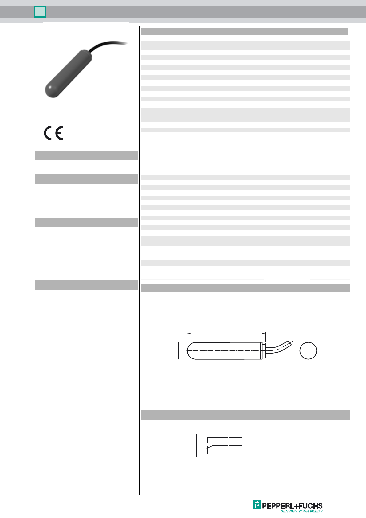
Dimensions
resistive load
4
switching cycles
EN 60947-5-1:2004 + Cor.:2005 + A1:2009
circuit can support the electrical circuit values of the switching
elements.
range of application and minimum length between mounting and
float:
≥ 100 mm (4 inch), preferred for fuels, heating oils, oily fluids
mounting:
- The float switch is mounted either from sidewards through a cable
gland ≥ G1A into the vessel or
- by means of a counter weight or rods (e. g. float switch
combination) from the top.
The pivot of the cable should always be horizontal.
≤ 3 bar (43.5 psi) at 20 °C (68 °F)
≥ 0.8 g/cm
5 m
cable: PUR, highly flexible (3 x 0.50 mm
- upper switch point +25° ±10°
- lower switch point -14°±10°
Conformity and instr ved where applicable.
For information see
3
2
)
Release date: 2017-11-15 11:12 Date of issue: 2017-11-15 262201_eng.xml
Refer to “General Notes Relating to Pepperl+Fuchs Product Information”.
135
ø 29.2
Electrical Connection
BU
BK
BN
1
Float Switch LFL2-CK-U-PUR5-EMS
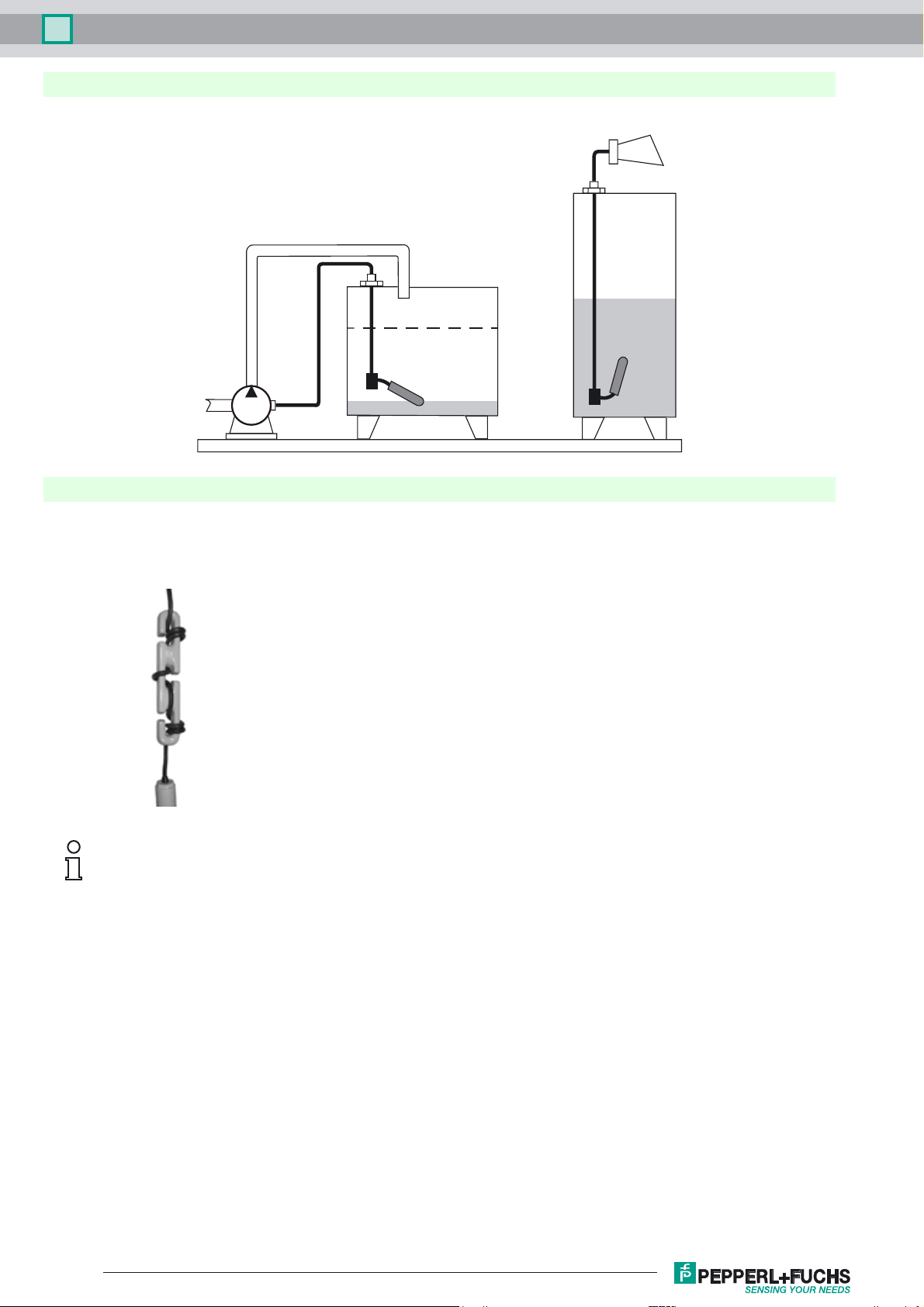
Application
Controlling pumps and valves with one switch or signal level height or limit
Mounting
Mount the float switch in the following way:
• Insert the float switch into the tank through a tapped hole G1A.
• Srcew the float switch with the gland screw connection G1A.
• If it is installed from above, use the counter weight LFL-Z32 or LFL-Z33 for mounting.
The fulcrum of the cable should always be horizontal.
The cable length between the fixture and the floating body is dependent on the cable type.
When using the counter weight, place an extra strain relief (e. g. a knot in the cable) behind the gland screw connection
– on the outside of the tank.
Release date: 2017-11-15 11:12 Date of issue: 2017-11-15 262201_eng.xml
Refer to “General Notes Relating to Pepperl+Fuchs Product Information”.
2
 Loading...