

Page 1
Loop detector
80 41
78
76
Germany: +49 621 776 1111Pepperl+Fuchs Group
Refer to "General Notes Relating to Pepperl+Fuchs Product Information".
USA: +1 330 486 0001 Singapore: +65 6779 9091
www.pepperl-fuchs.com fa-info@us.pepperl-fuchs.com fa-info@sg.pepperl-fuchs.com
fa-info@de.pepperl-fuchs.com
LC20-2-RB 230VAC
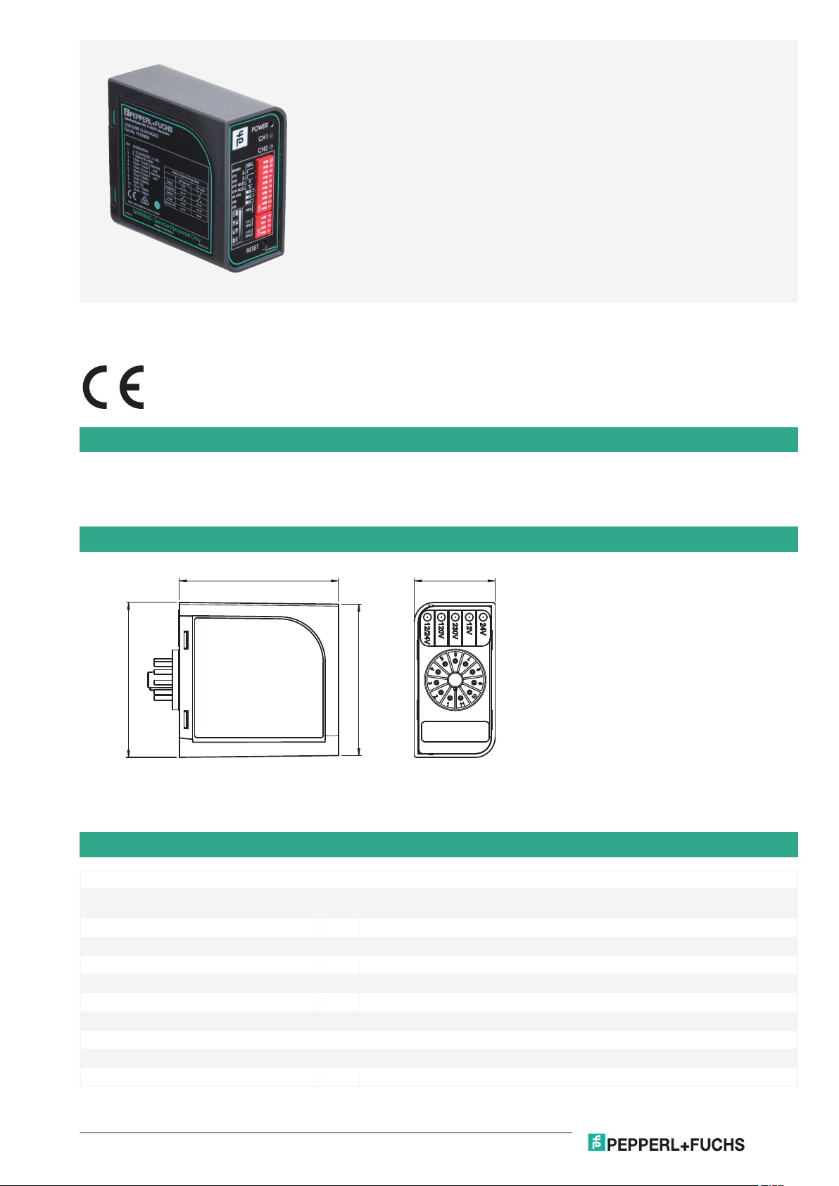
Sensor system for vehicle detection
<
Complete control interface for inductive loops laid beneath the
<
surface
Reliable detection with long service life
<
Boost function for increasing sensitivity
<
Test function
<
Version with 2 loop channels
<
Version with direction detection
<
Sensor system for detecting vehicles, two loops, plug-in base mounting, 230 VAC
Function
In combination with wire loops laid in the floor, loop detectors form a universal sensor system for detecting vehicles. When vehicles drive onto the
loop, the resonance frequency changes. Intelligent automatic frequency selection (AFS) reduces setup time and simplifies the installation of
complex multi-lane entrances. The evaluation process automatically and cyclically adjusts to the respective loop, so that changes in loop
inductance due to temperature, humidity or component ageing are automatically compensated.
Dimensions
Technical Data
General specifications
Adjustment range Sensitivity ΔL/L 4x adjustable on the front panel
Function principle Inductive loop
Marking CE
Presence time One hour for 3 % ΔL/L and option for permanent presence
Self-tuning range 20 μH ... 1500 μH
Operating frequency 4x adjustable on the front panel: 12 kHz ... 80 kHz (with AFS switched off)
Operating mode Pulsed and continuous signal
Indicators/operating means
Function indicator 1 x red LED: Power supply/Status , 2 x green LED: Channel status
Control elements DIP-switch , Refer to the documentation for functions
Release date: 2020-10-08 Date of issue: 2020-10-08 Filename: 70100659_eng.pdf
0.01 % ... 0.1 % with ASB overwrite option
1
Page 2

Loop detector LC20-2-RB 230VAC
Germany: +49 621 776 1111Pepperl+Fuchs Group
Refer to "General Notes Relating to Pepperl+Fuchs Product Information".
USA: +1 330 486 0001 Singapore: +65 6779 9091
www.pepperl-fuchs.com fa-info@us.pepperl-fuchs.com fa-info@sg.pepperl-fuchs.com
fa-info@de.pepperl-fuchs.com
Technical Data
Switching state LED
Electrical specifications
Operating voltage U
No-load supply current I
Power consumption P
Input
Number of channels 2
Output
Signal output One configurable relay output per channel
Switching current Relay outputs 1 A at 230 V AC
Pulse length 150 ms or 250 ms (selected via switch)
Response time 200 ms ... 300 ms
Directive conformity
Radio and telecommunication terminal
equipment
Approvals and certificates
FCC approval FCC 47 CFR Part 15
Ambient conditions
Operating temperature -40 ... 70 °C (-40 ... 158 °F)
Storage temperature -40 ... 70 °C (-40 ... 158 °F)
Relative humidity max. 90 % , non-condensing
Mechanical specifications
Degree of protection IP30
Connection 11-pin plug-in base
Material
Housing ABS, anthracite
Installation 11-pin plug-in base
Mass 250 g
B
0
0
230 V AC ±15 %
∅ 10.9 mA
∅ 2.5 VA
2014/53/EU
Release date: 2020-10-08 Date of issue: 2020-10-08 Filename: 70100659_eng.pdf
2
Page 3
1
2
3
4
5
6
7
8
9
10
11
Relay 2
Power
Loop 2
Loop 1
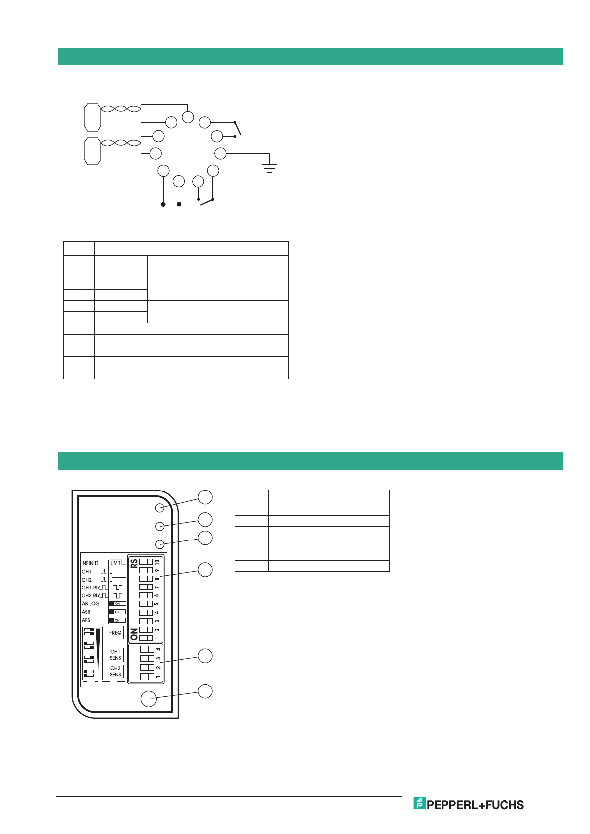
Pos. No.
11-pole connector
Function
1 Power supplyL
2 N 230 V ±10% AC 50/60 Hz
Twist pair 5 + 6
3
4
5
6
7
Loop 2
8
Loop 2
Twist pair 3 + 4
Loop 1
Loop 1
9 Earth
10 NO relay contact 1
11 NO relay contact 1
NO relay contact 2
NO relay contact 2
Relay 1
N L
POWER
CH1
CH2
RESET
1
2
3
4
5
6
Pos. No. Operating Elements
1 LED power supply
2 LED channel 1
3 LED channel 2
4 DIP switch
5 DIP switch channel 1 and 2
6 Reset button
Loop detector LC20-2-RB 230VAC
Germany: +49 621 776 1111Pepperl+Fuchs Group
Refer to "General Notes Relating to Pepperl+Fuchs Product Information".
USA: +1 330 486 0001 Singapore: +65 6779 9091
www.pepperl-fuchs.com fa-info@us.pepperl-fuchs.com fa-info@sg.pepperl-fuchs.com
fa-info@de.pepperl-fuchs.com
Connection Assignment
Assembly
Release date: 2020-10-08 Date of issue: 2020-10-08 Filename: 70100659_eng.pdf
3
Page 4

Loop detector LC20-2-RB 230VAC
Germany: +49 621 776 1111Pepperl+Fuchs Group
Refer to "General Notes Relating to Pepperl+Fuchs Product Information".
USA: +1 330 486 0001 Singapore: +65 6779 9091
www.pepperl-fuchs.com fa-info@us.pepperl-fuchs.com fa-info@sg.pepperl-fuchs.com
fa-info@de.pepperl-fuchs.com
Application
Matching system components
LC20-DT Bluetooth diagnostic unit for installation and diagnostics of LC20 detection loops
Release date: 2020-10-08 Date of issue: 2020-10-08 Filename: 70100659_eng.pdf
4
Page 5

Germany: +49 621 776 1111Pepperl+Fuchs Group
Refer to "General Notes Relating to Pepperl+Fuchs Product Information".
USA: +1 330 486 0001 Singapore: +65 6779 9091
www.pepperl-fuchs.com fa-info@us.pepperl-fuchs.com fa-info@sg.pepperl-fuchs.com
fa-info@de.pepperl-fuchs.com
Relay
Fail Secure Fail Safe
Relay
Loop not covered
Loop covered
Error
Power off
(No detection)
(Detection)
Release date: 2020-10-08 Date of issue: 2020-10-08 Filename: 70100659_eng.pdf
Loop detector
LC20-2-RB 230VAC
Programming
Teach-In
Presence Time: DIP Switch 10
The presence time setting determines how the detector tracks a detect. The following two selection modes are available:
permanent presence and limited presence.
• Permanent presence mode: This setting maintains the presence of a vehicle over the loop by continuously compensating for
all environmental changes.
• Limited presence mode: This setting limits the presence of a vehicle over the loop with the presence time being related to the
size of the detect.
Typically, a 1 % L/L will time out after approximately 1 hour.
Pulse on Detect or Presence on Detect: DIP Switch 9 - 8
The pulse relay offers the following settings:
• Pulse on detect: After 150 ms, the relay issues a pulse when detecting a vehicle drives on the loop.
• Presence on detect: Relay issues a pulse during the entire period a vehicle is detected.
This setting can be made for each channel respectively as indicated on the faceplate.
Fail-safe or Fail-secure: DIP Switch 7-6
Determine how the relay output of the presence relay is switched. Set the DIP switch to "Fail-Safe" or "Fail-Secure".
• Fail-safe setting: The output of detect is equivalent to powering off the sensor. This setting is used for access controls if
persons are not to be locked out in the event of a power failure. A signal is output due to a valid detection situation or in the
event of a power failure/ an error.
• Fail-secure setting: The output of non-detect is equivalent to powering off the sensor. This setting is used for access controls
if persons should not be able to access the sensor in the event of a power failure. A signal is only issued due to a valid detection
situation.
AB Logic: DIP Switch 5
Use AB Logic to count the cars going in a specified direction:
• 150 ms pulse output on Relay 1: Indicates a transition from loop 1 to loop 2 (classified as forwards).
• 150 ms pulse output on Relay 2: Indicates transition from loop 2 to loop 1 (classified as backwards).
Automatic Sensitivity Boost (ASB): DIP Switch 4
Use ASB to alter the undetect level of the sensor if required.
• ASB on: Boosts the sensitivity level to a maximum for detecting a vehicle, irrespective of the current sensitivity level maintained
at this level during the entire presence of the vehicle over the loop. When the vehicle leaves the loop and the detection is lost,
the sensitivity level reverts to the pre-selected level. ASB is used for vehicles with high beds or vehicles towing trailers to
ensure detection over the entire length of the vehicle.
• ASB off: Sensitivity level remains unboosted during detection.
Automatic Frequency Selection (AFS): DIP Switch 3
Decide whether to use AFS or not.
• AFS on: The detector briefly evaluates all 5 frequency bands and selects the best operating frequency available. The tuning
• AFS off: Select the frequency manually.
Manual Frequency Selection: DIP Switches 1-2
Use the frequency switches to set the operating frequency of the detector. If more than one detector is used at the same location,
time with AFS switched on ranges between 5 s … 20 s.
5
Page 6

Germany: +49 621 776 1111Pepperl+Fuchs Group
Refer to "General Notes Relating to Pepperl+Fuchs Product Information".
USA: +1 330 486 0001 Singapore: +65 6779 9091
www.pepperl-fuchs.com fa-info@us.pepperl-fuchs.com fa-info@sg.pepperl-fuchs.com
fa-info@de.pepperl-fuchs.com
Loop detector
LC20-2-RB 230VAC
it is necessary to set a different frequency for each detector to avoid crosstalk (interference) between adjacent loops connected
to different detectors. Make sure that the loops of the detectors used are at least 2 m apart between the adjacent ends. Set each
detector used at the same location to a different frequency.
The loop interfaces of multi-channel detectors are designed in a way that the loops are immune to crosstalk.
DIP Switch 4 DIP Switch 3 Frequency
Right Right High frequency
Left Right Medium high frequency
Right Left Medium low frequency
Left Left Low frequency
Sensitivity: DIP Switches 1-4
The sensitivity of the detector determines the change in inductance required for detection. The loop detector offers up to 4
sensitivity settings. Sensitivity is defined as the change in inductance. The inductance of the loop detector ranges from
0.01 % ... 0.1 %, where 0.01 % corresponds to the highest sensitivity level.
DIP Switch 4 DIP Switch 3 Sensitivity
right right (0.01 %) - high sensitivity
left right (0.02 %) - medium high sensitivity
right left (0.05 %) - medium low sensitivity
left left (0.10 %) - low sensitivity
DIP Switch 2 DIP Switch 1 Sensitivity
right right (0.01 %) - high sensitivity
left right (0.02 %) - medium high sensitivity
right left (0.05 %) - medium low sensitivity
left left (0.10 %) - low sensitivity
Use
Operation
Push Button for Detector Reset and for Accessing Power Failure Function
Use the multipurpose button either to reset the detector if required or to access the power failure function. The loop detector has
a power failure function. In the event of a power failure, the function detects a present vehicle on the loop. This function is
designed for fail-safe situations to maintain pulse output status and prevent pulse output failure in the event of a power failure.
Use the Reset push button in the following cases:
• Reset the detector.
• Switch the power failure function on/off.
The function of the reset push button depends on the duration of pushing it down (=holding time):
Operating
element
Push button Reset 3 s Starts the reset of the detector.
Functional Principle
Loop detectors are control devices that are fully functional by connecting the supply voltage and an induction loop without the
requirement of any additional devices. The induction wire loop laid in the floor has the inductance of a high-frequency oscillating
circuit. When a vehicle drives or stands on the wire loop, the vehicle's metal parts change the frequency of the oscillating circuit.
The loop detector evaluates this change and outputs it as a switching signal via volt-free relay contacts. The switching outputs
are relay contacts with a high switching capacity. The spatial extent of the detection range can be varied by the size and shape
of the induction loops used.
Release date: 2020-10-08 Date of issue: 2020-10-08 Filename: 70100659_eng.pdf
Purpose Holding time Function description
Show power
fail state
Power Fail
Toggle
10 s Hold for 10 seconds, to analyze the state of the
power fail.
If LEDs are ON, the Power Fail Toggle is ON.
If LEDs are OFF, the Power Fail Toggle is OFF.
30 s After 30 seconds the Power Fail Toggle is OFF if
the LEDs turn OFF.
If the LEDs turn ON after 30 seconds, the Power
Fail Toggle is ON.
6
Page 7

Germany: +49 621 776 1111Pepperl+Fuchs Group
Refer to "General Notes Relating to Pepperl+Fuchs Product Information".
USA: +1 330 486 0001 Singapore: +65 6779 9091
www.pepperl-fuchs.com fa-info@us.pepperl-fuchs.com fa-info@sg.pepperl-fuchs.com
fa-info@de.pepperl-fuchs.com
Loop detector
Application
• Park barrier control
• Safety loop
• Arming control
• Motorized gates and doors
• Industrial control systems
LC20-2-RB 230VAC
Release date: 2020-10-08 Date of issue: 2020-10-08 Filename: 70100659_eng.pdf
7
 Loading...